



Cars with 1.6-/2.0 liter petrol engine
The electronic multi-point injection system has four injectors, one for each cylinder. The injectors inject fuel into the intake valves sequentially, each one individually in accordance with the engine operating order. In a 1.6-liter engine (K7M), injection occurs semi-sequentially. This means that injectors I and 4, 2 and 3 cylinders operate simultaneously. The current position of the pistons of the cylinders is communicated to the control unit by two pulse sensors. One sensor is located on the flywheel, and the other registers the position of the camshaft.
Fuel is taken from the fuel tank by an electric fuel pump and fed through a fuel filter into the fuel distribution line, and from there to the injectors. A pressure reducing valve on the fuel distribution line maintains the pressure in the fuel system at a constant level of 3 bar.
The main indicator that determines the volume of injected fuel for the control unit is the vacuum in the intake manifold. This vacuum depends on the throttle opening angle at the current moment, as well as on the number of engine revolutions. These two indicators are a measure of the volume of air taken in. The pressure sensor in the intake manifold is located on the bulkhead of the engine compartment and is connected to the intake manifold by a hose (see illustration 1.0a).
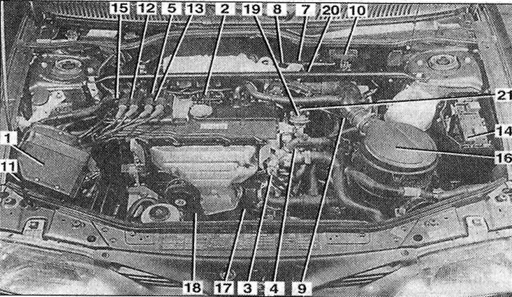
1.0a Engine compartment of a car with a 1.6-liter gasoline engine (K7M): I - control unit; 2 - knock sensor; 3 - coolant temperature gauge sensor; 4 - TDC sensor; 5- adsorber valve; 7 - idle speed controller; 8 - throttle potentiometer; 9 - intake air temperature sensor; 10 - intake manifold pressure sensor; 11 - adsorber; 12 - ignition coil of cylinders 1 and 4; 13 - ignition coil of cylinders 2 and 3; 14 - fuel pump relay; 15 - noise suppression capacitor; 16 - air filter; 17 - lambda probe (oxygen sensor); 18 - Power steering switch sensor; 19 - EGR valve; 20 - Air pump; 21 - air filter
Additional information regarding the throttle valve opening angle is supplied to the control unit by the potentiometer. This information serves as a comparative value for the volume of incoming air. It is needed so that the control unit can react to changes in the driving pattern, for example, to acceleration, or is used when the control unit switches to the so-called emergency program in the event of failure of the pressure sensor in the intake manifold.
The ignition and injection control unit, based on information about the volume of incoming air and the current engine speed, sets the injection duration and thus the amount of injected fuel, guided by the embedded parametric and data. If the injectors remain open for a longer period of time, the volume of injected fuel also increases. Additional sensors regulate the fuel volume in relation to the corresponding engine load at the current moment.
The idle speed control sensor informs the control unit about the throttle position at idle. The control unit adjusts the idle speed to the nominal values via the regulator.
The idle speed control valve, which is an electromagnetic valve, regulates the air supply bypassing the throttle valve, which stabilizes the idle speed under any conditions and any load.
The coolant temperature gauge sensor, located in the exhaust manifold, measures the engine temperature, and the air temperature sensor in the intake manifold measures the temperature of the air taken in by the engine.
The oxygen sensor is screwed into the exhaust pipe and measures the oxygen content in the exhaust gas. Based on the information received from this sensor, the control unit maintains the exhaust gas composition in the most acceptable values for the sensor.
The electromagnetic valve of the fuel tank ventilation is activated depending on the engine load. Fuel vapors from the tank are captured by the adsorber, which is a container with activated carbon, and through the electromagnetic valve are fed to the engine for combustion.
Cars with a 1.6 liter engine and a 16 valve engine
The EGR valve is located in the exhaust manifold and opens when the engine is hot to allow a certain amount of fresh air to enter, which is mixed with the exhaust gases. This is necessary so that this air is burned before the exhaust gases enter the catalytic converter. This reduces harmful carbon oxides in the exhaust gases.