
Note. To prevent breakage of the contact disc under the steering wheel, the following instructions must be observed:
- before disconnecting the steering shaft from the steering mechanism, be sure to block the steering wheel and wheels in the straight ahead position with the steering wheel locking device, and the steering wheel and wheels must remain locked during the entire time of work;
- if the alignment of the contact plate was not performed correctly, it is necessary to remove the steering wheel to perform the alignment procedure again.
Place the car on a lift.
Remove:
- top cover of the engine;
- windshield wiper arms;
- air intake grille;
- a box under the grille of the air intake niche;
- battery;
- battery shelf;
- air filter housing.
Loosen the clamp on the air inlet pipe on the throttle valve. Disconnect and remove the outlet air duct from the air filter housing.
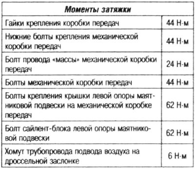
Disconnect:
- cables for selecting and shifting gears from the manual gearbox by pressing the latches (1);
- selector and shift cables by pressing at a point (2).
Set aside the manual transmission selector cables.
Install Pipe Pliers (Ms. 583) to the supply pipeline of the hydraulic clutch at the outlet of the brake fluid reservoir. Remove the clutch hydraulic line.
Disconnect the reversing light switch connector.
Remove:
- a message tube with the atmosphere of a manual transmission;
- front wheels;
- the front of the front fender liner;
- engine crankcase mounting bolts;
- engine undertray protection;
- front bumper.
Drain the fluid from the manual transmission.
Remove:
- starter;
- lower jet thrust;
- engine crankshaft position sensor;
- drive shaft of the left front wheel;
- right front wheel drive shaft;
- differential flange seals;
- crossbar for mounting the radiator.
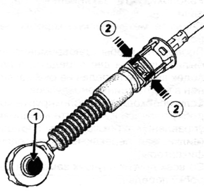
Install an adjustable support bar with retaining straps to hang the engine (Mot. 1453) with an additional nut with a handle mounted on it to the engine hoist Mot. 1453 and with safety strap.
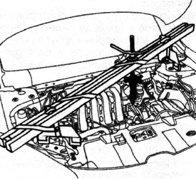
Disconnect the battery harness groove in the area (3).
Move aside the battery harness groove.
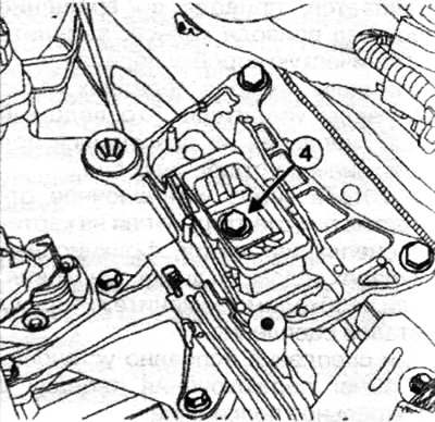
Remove the bolt (4) fastening the silent block from the left support of the pendulum suspension on a manual gearbox.
Slightly lower the manual transmission.
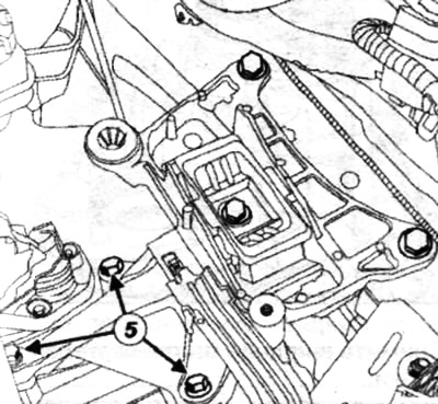
Remove:
- bolts (5) covers of the silent block of the left support of the pendulum suspension on a manual gearbox;
- the cover of the left pendulum suspension support on a manual gearbox.
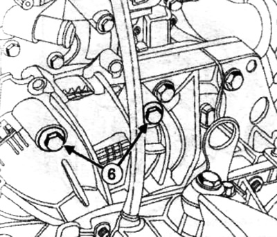
Loosen the upper bolts of the manual transmission (6).
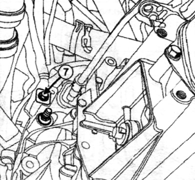
Note. Before removal «mass» terminal, mark its position by using an indelible pencil to draw a line from «mass» terminals to the gearbox housing.
Wrong position when assembling «mass» terminals on the gearbox housing can damage it or the wire «masses». Remove the bolt (7) mounts «mass» manual transmission wires.
Remove the wire «masses» with MCP. Establish the support device for removal and installation of transmissions (Bvi. 1718) on the hydraulic jack, then place the jack and support under the gearbox.
Tighten the linkage counterclockwise to prevent the manual transmission from rocking.
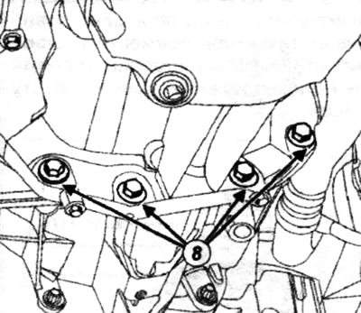
Loosen the bottom mounting bolts (8) manual transmission.
Remove:
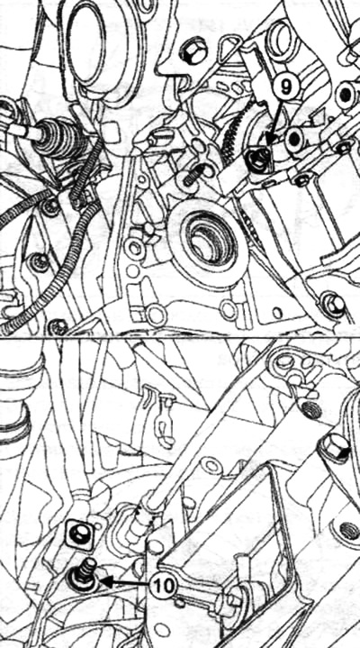
- MCP nuts (9) And (10);
- manual transmission.
Note. When replacing a manual transmission, remove the reverse light switch.
Note. If any stud has become loose during work, apply Frenetanche to its threads.
Tighten to the required torque of 7 Nm.
When installing a support tool for removing and installing gearboxes (Bvi. 1718) to a new manual transmission, repeat the steps for removal.
Install all parts in reverse order.