
Identification data
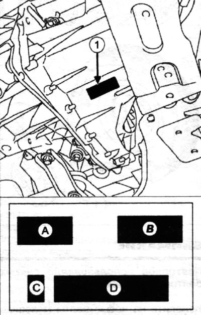
On the plate (1), fixed on the gearbox housing, are indicated:
- A - type of gearbox;
- B - gearbox index;
- C - manufacturer;
- D - serial number.
Precautions while working with the MCP
All work on the gearbox must be carried out in a clean environment.
Thoroughly clean the gearbox before opening it.
Repair the transmission in a clean room or clean work area.
During breaks in work, carefully cover the open gearbox to prevent foreign particles from entering it.
Removal of parts and actions with them should be carried out on a work table with a shock-resistant coating (thick rubber or plastic).
Lubricate all rotating parts and synchronizer parts by immersion in the brand of oil used.
Observe the tightening torques for screw connections.
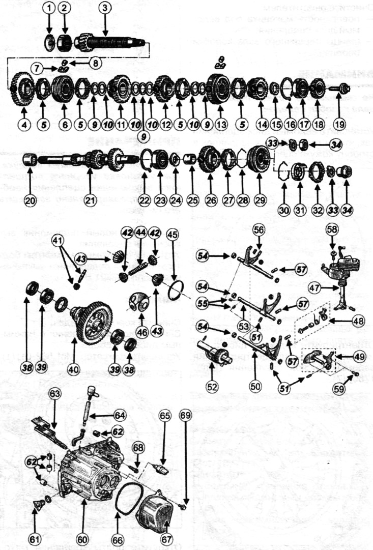
MCP components (JH3):
1— oil deflector;
2, 17, 23, 39 - bearing;
3 - secondary shaft;
4 - gear wheel of the 1st gear;
5 — a blocking ring of the synchronizer;
6 - hub of the synchronizer of the 1st and 2nd gears;
7, 28, 30 - spring;
8 - cracker;
9 — coupling collar;
10 - gear washer;
11 - gear 2nd gear;
12 - gear 3rd gear;
13 - hub and synchronizer clutch of 3rd and 4th gears;
14 - gear 4th gear;
15 - thrust washer;
16 - retaining rings;
18 - gear wheel of the 5th gear;
19 — a bolt of the back end of a secondary shaft;
20 - support ring;
21 - wheel drive shaft;
22 - retaining rings;
24 - thrust washer;
25 - gear bushing;
26 - gear 5th gear;
27 - synchronizer blocking ring;
29 - synchronizer hub;
31 - friction cone;
32 - synchronizer blocking ring;
33 - washer;
34 - input shaft nut;
38 - differential flange seal;
40 - differential;
41 - tachometer drive gear, if any);
42 - remote control;
43 - side gear;
44 - axis;
45 - axle retaining spring;
46 - clip;
47 - gear shift shaft;
48 - leash;
49 - rod and fork for turning on the reverse brake;
50 - rod and fork of the 5th gear;
51 - pin;
52 — the axis of the reverse gear;
53 - rod and fork for switching 3rd and 4th gears;
54 - sleeve; 55,
57 - retainer;
56 - rod and fork for switching 1st and 2nd gears;
58 — a bolt of fastening of a shaft of a gear change;
59 — a bolt of fastening of a rod of a plug of inclusion of a backing;
60 - gearbox housing;
61 - oil filler plug;
62 - spacer;
63 - oil supply chute;
64 - breather tube;
65 - reverse light switch;
66 - sealing ring;
67 — back cover;
68 — a bolt of fastening of a case of a transmission;
69 — a bolt of fastening of a back cover.
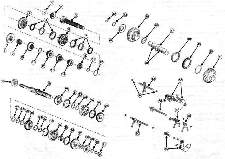
MKL components (TL4):
1 - oil deflector;
2 - bearing;
3 - secondary shaft;
4 - driven gear 1st gear;
5 - blocking rings of the three-cone synchronizer;
6 - hub of the synchronizer of the 1st and 2nd gears;
7 - blocking rings of the three-cone synchronizer;
8 - driven gear 2nd gear;
9 - gear bushing;
10 - driven gear 3rd gear;
11 - intermediate adjusting ring;
12 - drive gear 4th gear;
13 - drive gear of the 5th gear;
14 - drive gear of the 6th gear;
15 - bearing;
16 — coupling collar;
17 - adjusting ring bearing preload;
18 - bearing;
19 - wheel drive shaft;
20 - driven gear 3rd gear;
21 - synchronizer blocking ring;
22 - toothed washer;
23 — coupling collar;
24 - hub and synchronizer clutch of 3rd and 4th gears;
25 - synchronizer blocking ring;
26 - driven gear 4th gear;
27 - gear washer;
28 — coupling collar;
29 - gear washer,
30 - driven gear of the 5th gear;
31 - gear washer;
32 — coupling collar;
33 - synchronizer blocking ring;
34 - hub and synchronizer clutch of the 5th and 6th gears;
35—needle bearing driven gear 6th gear;
36 - synchronizer blocking ring;
37 - driven gear 6th gear;
38 - thrust washer;
39 - bearing;
40 - retaining ring (old modification);
41 - hollow bolt (new performance);
42 - elastic washer installed in the clutch housing (observe the direction of installation - the convex side is facing the stem; reverse gear view);
43 — coupling collar;
44 - needle bearing;
45 - reverse drive gear;
46 - thrust bearing;
47 —axis reverse gear;
48 - return spring;
49—synchronizer blocking ring;
50 — coupling collar;
51 - sliding reverse gear;
52 - needle bearings mounted on the reversing axis;
53 — a rod of a fork of inclusion of a backing;
54 - plug stem;
55 - gear selection shaft;
56 - plug stem;
57 - shift fork 3rd and 4th gear;
58 - shift fork 5th and 6th gear,
59 - drive shaft of the gear lever;
60 - shift fork 1st and 2nd gear.
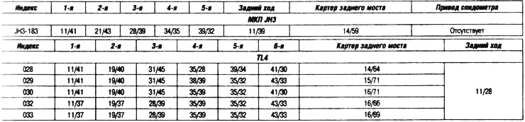
Gear ratios
Be careful when making adjustments. Install the removed parts in the same order and in the same position.
Before removal, mark the position of the synchronizer couplings relative to the hubs.
During assembly, take care to prevent dust or other contaminants from entering the gearbox.
Seats for oil seals must be absolutely clean, without traces of lubrication and damage. The seal fittings must be clean and free from grease.
Note. Install only bearings of the correct type in the gearbox (depending on the gearbox index).