
Removal
- Removal and installation are carried out on a two- or four-post lift without removing the sub-frame
- When removing the power unit, the following special tools must be used:
- centering fork of the pendulum suspension travel limiter Mot. 1289-02;
- pliers for elastic clamps Mot. 1202;
- keys for disconnecting the fittings of the power steering system pipelines located on the steering mechanism Dir. 1282-01+02;
- bits for knocking out elastic pins Bvi. 31-01;
- Tav ball joint remover. 476;
- Also, when removing the power unit, you must use the following equipment:
- impact ball joint remover:
- wheel chocks;
- device for disconnecting refrigerant pipes NAUDER 7240 and 7242;
- universal adjustable supports.
- Removal of the power unit is carried out by lowering it down and requires preliminary removal of the front bumper and a set of cooling system elements.
- Place the vehicle on a two-post lift equipped with FOG wheel chocks.
- Use the charging station to discharge the refrigerant from the air conditioning circuit.
- Remove:
- battery and its shelf-tray;
- cover of the switching unit:
- air filter;
- front wheels;
- front bumper.
- Disconnect the connector from the automatic transmission control unit.
- To facilitate access to the engine control unit, remove the battery cover (together with automatic transmission control unit).
- Remove:
- radiator trim (D. fig. 2.38), extensions and radiator grille (WITH);
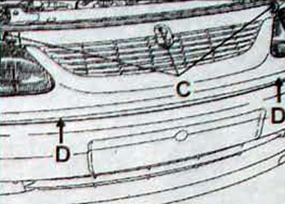
Pic. 2.38. Location of the radiator trim screws (D) and radiator grilles (WITH)
- protective guards for wheel arches;
- protective shields under the engine.
- Remove the set of cooling system elements by disconnecting the electrical wiring harness connectors from the electric motors of the engine cooling system fan group, the three-function pressure switch of the air conditioning system and the thermal switch on the radiator
- Remove the wiring harness
- Unscrew the 4 screws securing the deflectors to the side member (pic. 2.39).
Pic. 2.39. Location of deflector mounting screws
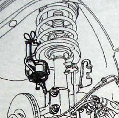
Pic. 2.40. Fastening the brake caliper to the front suspension spring
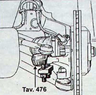
Pic. 2.41. Using the Tav puller. 476 to disconnect the tie rod end from the steering knuckle
- Attach the deflectors to the cooling system element kit.
- Drain the engine cooling system.
- disconnecting the upper radiator hose,
-move the lower radiator hose down onto the engine and plug the holes.
- Disconnect the air conditioning system pipes from the receiver-dryer (be sure to plug the holes).
Raise the car.
- Use two people to remove the cooling system element kit (2 bolts under the ends of the side members).
- Partially drain the oil from the final drive housing.
- Remove the drive shafts with brake discs and steering knuckles as follows:
- remove the brake calipers and secure them to the suspension springs;
- disconnect the ABS sensors;
- Unscrew the nuts of the bolts securing the lower supports of the shock absorber struts to the steering knuckle;
- disconnect the tie rod ends and lower step joints from the steering knuckles using a fav puller. 476.
On the left side of the car.
- Unscrew the 3 bolts securing the corrugated protective cover of the drive shaft to the differential flange (pic. 2.42). Remove the bolts of the lower mounting of the shock absorber strut to the steering knuckle and remove the drive shaft - steering knuckle - brake disc assembly (pic. 2.43).
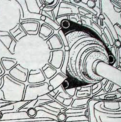
Pic. 2.42. Location of bolts securing the corrugated boot of the drive shaft to the differential flange
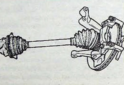
Pic. 2.43. Removing the drive shaft - steering knuckle - brake disc assembly from the vehicle
On the right side of the car.
- Unscrew the 2 bolts securing the locking plate to the intermediate support (pic. 2.44).
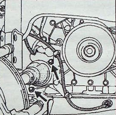
Pic. 2.44. Location of bolts securing the locking plate to the intermediate support
- Remove the drive shaft - steering knuckle - brake disc assembly. Protect the protective corrugated covers of the drive shaft from damage.
- Remove the exhaust pipe.
- Unscrew the tie rod bolt and disconnect «massive» tire from the gearbox.
- Drain the power steering system and the heat exchanger located under the vehicle.
- Using tool DIR 1282-01, disconnect the power steering pipes from the steering gear housing (liquid may leak out).
- Disconnect the speedometer connector from the transmission.
- Disconnect the air conditioning system pipes from the right engine swing arm.
- Remove the power steering reservoir and place it on the engine.
- Disconnect the low pressure hose from the air conditioning system at the bulkhead.
- Without cutting, remove the 3 plastic clamps securing the electrical wiring harness of the injection system control unit to the front panel.
- Remove the automatic transmission control unit wiring harness holders and secure the harness to the engine
- Remove the air intake pipe along with the aluminum bracket.
- Remove the intake manifold cover.
On the left side of the car
- Disconnect the accelerator cable from the throttle valve by using a screwdriver to disconnect the accelerator cable holder fastening.
- Disconnect the power steering high pressure hose bracket above the automatic transmission control cable ball joint.
- Remove the automatic transmission control cable by first disconnecting the ball end and removing the cable sheath bushing from the fastening tab by moving it up and back. towards the front panel (pic. 2.45)
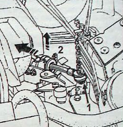
Pic. 2.45. Disconnecting the automatic transmission control cable: 1 - ball tip; 2 - directions for removing the cable sheath
- Disconnect the radiator hoses of the interior heating system from the engine (liquid may leak out)
Attention. If the quick release connectors are difficult to remove, first push in the connector while pressing down on the locking tabs before pulling it out. Do not allow hard tubes to form on the bulkhead.
- Disconnect the absolute pressure sensor (1 tube + 1 connector) on the front panel (in the upper left).
- Remove the expansion tank of the engine cooling system without disconnecting the hose and place the tank on
- Disconnect the vacuum hose from the brake booster (pic. 2.46).
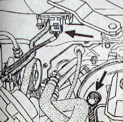
Pic. 2.46. Location of the absolute pressure sensor and the location of the vacuum hose attachment to the brake booster
- Disconnect the power steering low pressure hose from the rigid tube on the bulkhead.
- Disconnect the engine compartment wiring harness from the engine compartment wiring harness.
On the right side of the car
- Disconnect the absorber solenoid and disconnect the absorber hose from the mounting on the right engine pendulum mount.
- Remove the fuel line holder from the cylinder head.
- Disconnect the fuel lines.
From below the car
- Disconnect the connector from the oxygen concentration sensor.
- Prepare pipelines and electrical wiring for free removal of the power unit.
- Install the removal tool and carefully lift the vehicle until the power unit is suspended (do it together).
- Remove the right-hand pendulum engine mount mounting bracket.
- Remove the bolts securing the left engine pendulum mount.
- Free the engine from the mounts.
- Lower the power unit down while moving it forward a few centimeters.
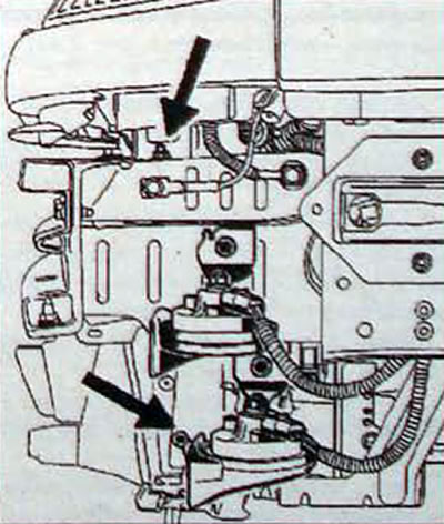
- Pay attention to the automatic transmission control cable when removing the power unit. Do not allow the cable to be pinched or damaged between the rear cylinder head and the right subframe beam in area A, fig. 2.47.
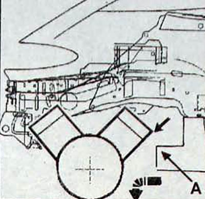
Pic. 2.47. Directions of movement when removing the power unit: A - right subframe beam
Installation
- Installation is carried out in the reverse order of removal.
- Using tool Mot. 1289-С2 adjust the position of the travel limiter of the right pendulum engine mount (pic. 2.48).
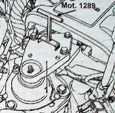
Pic. 2.48. Using tool Mot 1289-02 to adjust the position of the travel limiter of the right-hand pendulum engine mount (1)
- Run:
- pouring oil into the main gear housing;
- pouring oil into the engine;
- refueling the power steering system;
- filling and removing air from the engine cooling system;
- refilling the air conditioning system.
- Adjust the accelerator cable.
- Tighten the spring-loaded bolts of the clamps securing the exhaust pipe flanges (pic. 2.49).
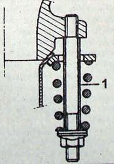
Pic. 2.49. Bolt (1) clamp for fastening the exhaust pipe flange
Attention. Tighten the bolts until they stop.
- Press the brake pedal several times until the pistons of the brake wheel cylinders contact the brake pads.
Attention. Don't forget to set the parameters "Pedal pressed" And "Pedal released" for reprogramming the operating parameters of the load potentiometer in the automatic transmission control unit.