
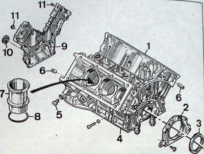
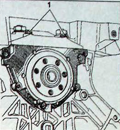
Pic. 2.50. Cylinder block:1 - cylinder block; 2 - rear cover of the cylinder block; 3 - rear crankshaft oil seal; 4 - main bearing cover; 5 - threaded plug for draining the cooling liquid; 6 - centering sleeve; 7 - cylinder liner; 8 - cylinder liner gasket 9 - timing cover; 10 - oil seal; 11 - plug
High mileage is not a sufficient indicator of the need for major repairs; on the other hand, low mileage does not exclude the need for major repairs. The most important indicator, apparently, is the timeliness of routine engine maintenance. With timely oil and filter changes, as well as all other necessary maintenance work, the engine will serve reliably for many thousands of kilometers. On the contrary, insufficient or untimely maintenance can cause a sharp reduction in engine life. Increased oil consumption indicates wear on the piston rings, valve guides and oil seals. You should make sure that leaks are not the cause of increased oil consumption, and only then draw a conclusion about the unsuitability of the piston rings and valve guides. To determine the probable cause of the malfunction, measure the compression in the engine cylinders. Also carry out tests using a vacuum gauge and determine the nature of the readings from this device.
Check the oil pressure with a pressure gauge screwed into place of the oil pressure sensor and compare the test result with the standard value. If the oil pressure is low, the cause may be worn main and connecting rod bearings or oil pump parts.
Loss of power, engine failure, detonation or metallic knocks. increased noise from the gas distribution mechanism, increased fuel consumption indicate the need for major repairs, especially if all these signs of abnormal operation appear simultaneously. If all adjustments do not lead to improvement, then the only remedy for abnormal engine operation is a major overhaul. Overhaul consists of restoring engine parts to the condition specified in the technical data for a new engine.
During an engine overhaul, such units as the starter, generator and ignition distributor are also repaired. As a result, the repaired engine must have the qualities of a new unit and withstand significant mileage without failures.
Before starting an engine overhaul, read the description of the relevant procedures to get an impression of the upcoming scope of work and the requirements for them. If you follow all the rules and regulations, and if you have all the necessary tools and equipment, major repairs are not difficult to carry out, but they will require a significant investment of time.
Disassembly
- Before disassembling, remove all attachments from the engine, such as the generator, manifolds, pipes, clutch and make sure that the engine oil is drained from the engine.
- During disassembly, it is very important to maintain cleanliness to prevent contamination of the disassembled components.
- Before disassembling, clean the outside of the engine with kerosene or. if the engine is very dirty, use solvent.
- When the parts are removed from the engine, wash them in kerosene.
- Never immerse parts that have internal lubrication channels in kerosene. Such parts should be thoroughly wiped with a cloth soaked in kerosene. The lubrication channels must be cleaned with a wire rope.
- If possible, mount the engine on a stand; otherwise, mount the engine in such a way that it will not be damaged when loosening tight nuts and bolts.
- Disconnect the transmission from the engine.
- Remove the timing gear drive.
- Use a steel rod to lower the cylinder head centering sleeve.
- Remove the cylinder head. In order not to disturb the cylinder liners, the head must be removed by turning it around the remaining guide sleeve. Because the gasket adheres to the cylinder head, cylinder block and liners, it is very important not to lift the head as this may cause the liners to come off their base and allow dirt to get inside
- Separate the head by tapping its edges with a plastic hammer in the direction of rotation in a horizontal plane.
- Remove the cylinder head gasket.
- Remove the second cylinder head in the same way.
- Using a steel hook (Renault Mot.587 fixture), remove the cylinder head guide bushings from the cylinder block.
- To prevent cylinder liners from moving when the cylinder head is removed, install a clamping bar (Renault Mot.588) on the upper edges of the cylinder liners
Note. If reusing liners and pistons, mark the direction of installation of the piston in relation to the liner and the front of the engine. Turn the engine over.
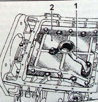
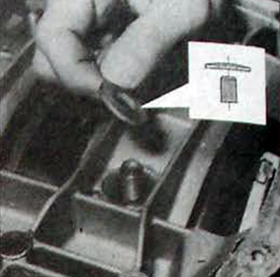
Pic. 2.51. Location of the oil intake pipe (1) with strainer and oil deflector plate (2)
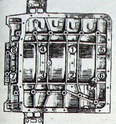
Pic. 2.52. Sequence of loosening the main bearing support bolts
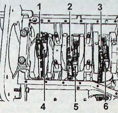
Pic. 2.53. Location and numbering of connecting rod caps
- Remove the oil pan, the strainer from the oil intake pipe and the oil deflector plate.
- In the reverse order of tightening, unscrew the bolts and remove the main bearing support.
- To hold the crankshaft in place, install two Renault Mot tools on the outer journals of the main bearings. 590.
- Mark the connecting rods with numbers, starting from the flywheel side of the engine, so that their numbering is identical to the numbering of the cylinders (1-4-2-5-3-6).
- Unscrew the bolts securing the lower connecting rod covers and remove the covers along with the liners.
- Remove the clamping bar (Renault Mot 588 fixture), securing the cylinder liners.
- Remove the liners with pistons and remove the pistons from the liners.
- Remove the 4 bolts securing the central main bearing caps.
- Check the markings on the main bearing caps and remove them.
- Remove the crankshaft, thrust washers and bearing shells and arrange them in the removal sequence.
Checking and repairing parts
- After disassembling the engine and cleaning all its parts from dirt and oil, they should be checked for signs of wear. Use Decaploc 88 Framet for cleaning and do not use sharp edged tools or abrasives
- In cases where a part does not have specified wear limits, it is necessary to decide whether the part should be replaced with a new one or whether it is suitable for further use. When making a decision, factors such as the expected service life of the engine, the required degree of reliability of the part and the amount of disassembly and assembly work that will be required in the future when replacing it are taken into account.
- Make sure the mating surfaces of the cylinder head and block are completely clean. Use a hard plastic or wooden scraper to clean them. Be careful when cleaning as aluminum alloy is very easy to damage. Make sure that carbon deposits do not get into the channels of the lubrication and cooling system. This is especially important for the lubrication system, since carbon deposits can block the flow of oil to engine parts. If necessary, clean the channels.
- Measure all reference dimensions of pistons, crankshaft, cylinder liners, etc. (see «Specifications»).
- Check the condition of the connecting rod bearing shells. A sign of damage to the connecting rod bearings is a regular rhythmic loud knock from the crankshaft, the frequency of which depends on the engine speed. This knocking noise is especially noticeable when the engine is running under load. This symptom is accompanied by a drop in oil pressure, although this is usually not noticeable unless an oil pressure sensor is installed.
- Check the condition of the main bearing shells. Bearing shells in good condition have a smooth surface and a uniform matte silver color over the entire surface. Worn liners have areas with different colors where the metal has worn away and the backing has exposed. Damaged earbuds have scratches or nicks. If the crankshaft itself is in good condition, then the issue can be easily resolved by purchasing another set of bearings of the same size. If the crankshaft is re-grinded or replaced, then this operation requires replacing the bearing shells. Bearing failure may be due to lack of lubrication, the presence of dirt or other foreign particles, engine overload, or corrosion. Regardless of the cause of bearing failure, the cause that caused the bearing failure must be corrected before the engine can be reassembled.
- When inspecting the bearings, remove them and place them in the same order as they were installed on the engine. This will allow you to identify the appropriate crankshaft journal and make troubleshooting easier.
- Foreign particles can enter the engine in various ways. Metal particles may be present in engine oil as a result of normal engine wear. Fine particles can enter the bearings along with the engine oil and easily become embedded in the soft bearing material. Large particles entering the bearing will scratch the bearing or crankshaft journal. The best way to prevent bearing failure for this reason is to thoroughly clean all internal surfaces of the engine and keep them clean when reassembling the engine. Frequent and regular oil and filter changes are also recommended
- Insufficient lubrication of the crankshaft journals can be caused by many different reasons, such as high oil temperature, engine overload and oil leakage.
- The driving style of the car also affects the durability of the bearing. A fully open throttle valve at low engine speeds creates a high load on the bearings and squeezes out the oil film from the contact zone. These loads lead to the appearance of cracks in the working part of the bearing, which weakens the bearing and can lead to separation of the antifriction layer from the steel base
- Short distance driving causes bearing corrosion as a result of the engine not reaching a stabilized operating temperature that removes water vapor and corrosive gases. These vapors and gases condense in the engine oil, forming acid and sediment. The acid, along with the engine oil, gets to the bearings and corrosion of the bearings begins.
- Incorrect selection of bearings during engine assembly also leads to bearing failure. Preloaded bearings leave insufficient bearing running clearance, resulting in a reduced or absent layer of oil for lubrication.
- Remove the piston rings from the pistons by carefully sliding them towards the top of the piston so as not to scratch the aluminum alloy. Never push the rings towards the piston skirt. Piston rings are easily damaged if removed carelessly. Therefore, this operation must be performed with extreme caution. You can use old probes. Lift one edge of the piston ring that needs to be removed from the groove and insert a dipstick underneath it. Slowly move the dipstick around the piston and... When the ring comes out of its groove, lift it up. Moreover, the dipstick will keep the ring from sliding into an empty groove, if there is one already.
- Check the condition of the pistons and connecting rods.
- Remove the connecting rod from the piston by removing one retaining ring and pressing out the piston pin.
- Check for marking marks on the connecting rods and lower connecting rod caps.
- If necessary, replace the connecting rod cap bolts and bushings in the upper connecting rod heads.
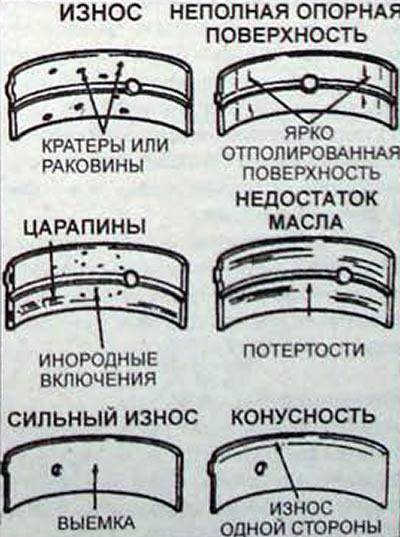
Pic. 2.54. Typical bearing defects
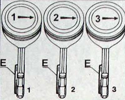
Pic. 2.55. Pistons 1, 2 and 3 cylinders with projection (E). shifted to the rear of the engine
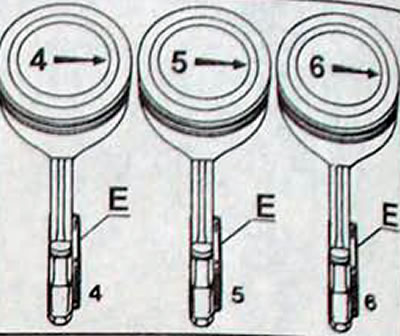
Pic. 2.56. Pistons 4, 5 and 6 with projection (E), shifted to the front of the engine
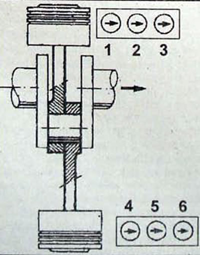
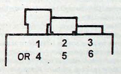
Pic. 2.57. Piston installation position
Assembly Recommendations
- To achieve maximum engine life after a major overhaul with a minimum of problems, it is necessary not only to assemble all the parts correctly, but all parts and components must be spotlessly clean, all lubrication channels must be clean. The lock washers and spring washers are in place. Bearings and other parts with sliding surfaces must be thoroughly lubricated during assembly.
- Before starting assembly, replace any bolts, studs or nuts that have damaged threads with new ones. It should also be replaced with new spring washers.
- Keep an eye on this during installation. so that the parts are installed in their original places. Also check the installation direction of the parts.
- The oil seal lips should be lubricated before installation.
- When installing gaskets, use sealant where required to prevent leakage
Piston and connecting rod assembly
- When assembling the piston with the connecting rod, it is necessary that the protrusion on the lower head of the connecting rod is located only on a certain side of the piston. To comply with this, the arrow on the bottom of the pistons of cylinders 1, 2 and 3 must be directed in the direction opposite to the location of the protrusion on the lower head of the connecting rod and, vice versa, for pistons of cylinders 4, 5 and 6.
- Lubricate the piston pins with clean engine oil and install them into the piston and connecting rod.
- Secure the piston pins with retaining rings.
Selecting the thickness of the cylinder liner gasket
- Before installing the piston and connecting rod into the cylinder liner, check the protrusion of the cylinder liners from the cylinder block.
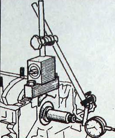
- Install liners without gaskets on the cylinder block. Using the support bar Mot. 252-01 and stands with dial indicator Mot. 251-01 check the amount of protrusion of each sleeve at points A and B (pic. 2.58).
- To obtain the theoretical value of the thickness of the spacer that needs to be installed under the sleeve from the recommended value of the sleeve protrusion, subtract the measured value
- Select a gasket of appropriate thickness or thinner (cm thickness of gaskets in «Technical specifications»). To ensure that the protrusion of the liners corresponds to the required values, gaskets of 4 different thicknesses are used, which are identified by color
- Remove the liners from the cylinder block and install a gasket of the appropriate thickness on each of them, making sure that the grooves of the gasket fit neatly into the groove.
- Install the liners so that the colored tabs on the lower seals are visible.
- The difference in the amount of protrusion of the cylinder liners from the cylinder block should not exceed 0.04 mm. In addition, the increase in protrusion should be directed in one direction.
- Once the projection is correct, assemble new sets of parts A, B, C, D, E and F, and then number the liners, pistons and piston pins 1 to 6 (starting from the flywheel side of the engine) so that the connecting rods are in the same place.
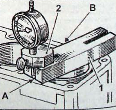
Pic. 2.58. Measuring the protrusion of liners from the cylinder block: 1 - support bar Mot. 252-01; 2 - dial indicator Mo 251-01; A and B - measuring points for the sleeve protrusions
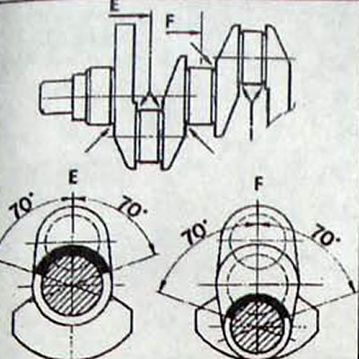
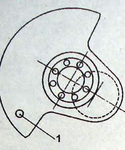
Pic. 2.59. Location of the 140°crankshaft area that cannot be reground (sections E and F are chosen as an example)
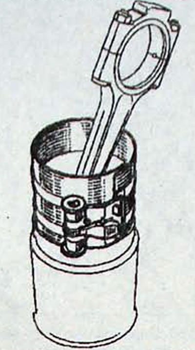
Pic. 2.60. Using a device to compress piston rings when installing a piston with connecting rod into a cylinder liner
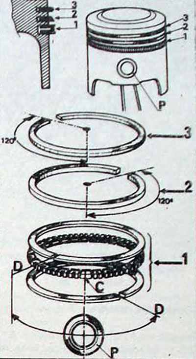
Pic. 2.61. Location of piston rings on the piston: 1 - oil scraper ring; 2 - second compression ring; 3 - first compression ring; C - ring lock; D - ring lock; P - piston pin
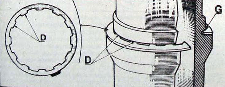
Pic. 2.62. Installing the gasket on the cylinder block liner, with the inner protrusions of the gasket (D) must fit into the groove (G) cylinder liners
Pic. 2.63. Recommended cylinder liner protrusion location
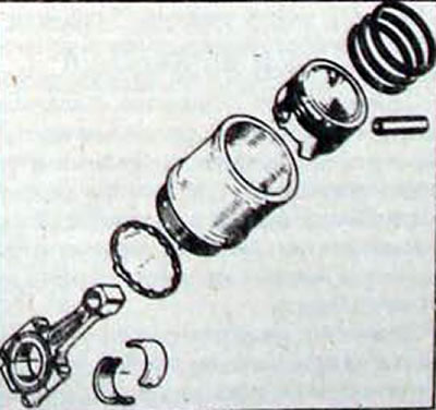
Pic. 2.64. Piston and cylinder liner parts
Crankshaft
Z7X engines have two types of crankshafts, differing in piston stroke. The crankshaft for a piston stroke of 72.7 mm has two marks:
- hole (1, fig. 2.65) on the counterweight on the flywheel side of the engine.
Pic. 2.65. Hole location (1) on counterweight on flywheel side of Z7X engine for 72.7mm stroke
Pic. 2.66. Checking the crankshaft end play
Pic. 2.67. Installing a special washer for the nut securing the main bearing cap with its convex surface towards the nut
- a dot painted with blue paint on the side of the gas distribution mechanism.
- Clean the crankshaft thoroughly.
- Inspect the main and connecting rod journals for signs of wear, marks and scratches. Check the ovality of the necks.
- Before reinstallation, the crankshaft must be thoroughly cleaned, including the internal oil passages. This can be done using wire or compressed air. Then insert the oil can into the corresponding oil passages and squeeze the oil into them. It should appear from the next hole. Any blockage in the oil passage must be cleared.
- Check the condition of the connecting rod bearings.
- Check the condition of the crankshaft journals working in contact with the sealing rings.
Engine assembly
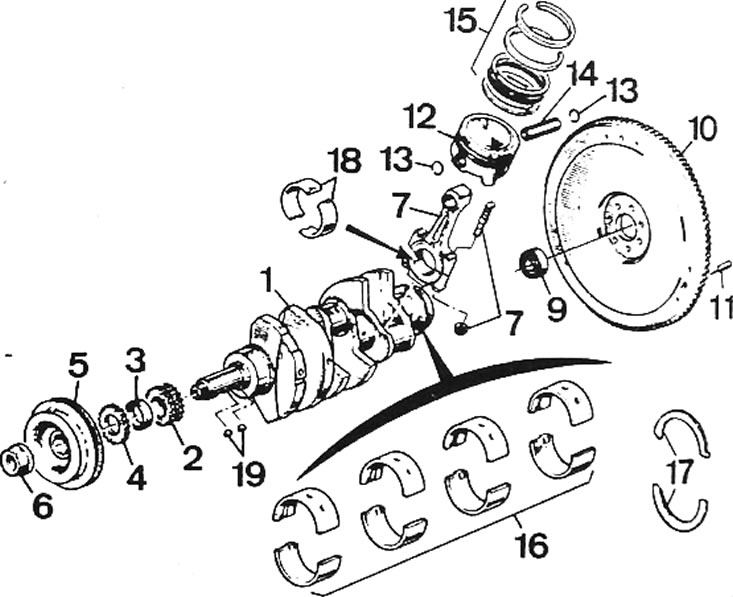
Pic. 2.68. Crankshaft, piston and connecting rod: 1 - crankshaft; 2 - drive sprocket; 3 - spacer sleeve; 4 - oil pump drive sprocket; 5 - crankshaft pulley; 6 - nut; 7 - connecting rod; 8 - connecting rod mounting bolt; 9 - needle bearing; 10 - flywheel; 11 - centering pin of the clutch pressure plate housing; 12 - piston; 13 - retaining ring; 14 - piston pin; 15 - piston rings; 16 - main bearing shells; 17 - thrust half-rings that limit the axial movement of the crankshaft; 18 - connecting rod bearing shells; 19 - segment key
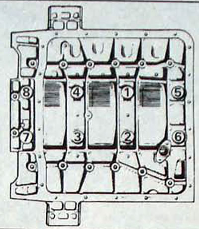
Pic. 2.69. Sequence for tightening the main bearing support nuts
Pic. 2.70. Location of the two bottom bolts (1) cylinder block rear cover fastenings that need to be tightened first
Note. When installing moving engine parts, pre-lubricate them with clean engine oil.
- Turn the engine over.
- Wipe the outer parts of the main bearing shells and their installation locations in the cylinder block. Insert the upper main bearing shells into the cylinder block without lubrication. Please note that the top liners have grooves. Check that the protrusion on each liner fits into the groove in the cylinder block.
- Clean the working surfaces of the main bearing shells and lubricate them with a thin layer of engine oil. Also lubricate the working surface of the crankshaft thrust half ring.
- When installing the thrust half-rings, note that there are marks on the upper half-rings. Install the upper thrust half-rings with a thickness of 2.30 mm.
- Lubricate the crankshaft main bearing journals with oil and install the crankshaft into the cylinder block.
- Orient the front and rear main bearing caps with the protrusions facing the timing drive. Insert the main bearings into the covers without lubrication. Clean the working surfaces of the main bearings and lubricate them with a thin layer of engine oil.
- Install the main bearing caps to tool Mot. 590 and tighten the cover fastening nuts to a torque of 30 Nm. Rotate the crankshaft and check for smooth movement.
- Move the crankshaft along the axis and check its axial play. Axial play of the crankshaft: 0.07 - 0.27 mm.
- If the axial play of the crankshaft differs from the permissible value, install thrust half-rings of a different thickness.
- Install the liner-piston-connecting rod assembly of the 1st cylinder into the cylinder block, with the arrow on the piston pointing towards the gas distribution mechanism drive.
- Install the connecting rod with the bushing onto the crankshaft journal.
- Install the connecting rod cover with the liner and tighten the cover fastening nuts by hand
- Install the temporary sleeve retainer
- In the same way, install the liners, pistons, connecting rods of the remaining cylinders into the cylinder block.
- Using the previously applied marks, check that the piston and connecting rod are installed correctly, with the arrow on the piston directed towards the gas distribution mechanism drive.
- Tighten the connecting rod cap nuts to the required torque.
- Make sure the crankshaft rotates smoothly and without binding.
- Remove the front and rear crankshaft main bearing caps.
- Install the intermediate main bearing caps, with the protrusions on the caps being on the drive side of the gas distribution mechanism.
- Install the rear cover with the crankshaft rear oil seal installed on the cylinder block and align the gasket with the mating surface of the oil pan. Secure the cover with the bolts, hand-tightening them.
- Install the oil pick-up pipe with a new gasket.
- Apply CAF 4/60 Thixo or Rhodorseal 5661 to the oil pan mating surface.
- Install the oil pan.
Note. When installing the oil pan, make sure that its front plane is level with the front plane of the cylinder block (maximum deviation 0±0.25 mm), which will ensure good tightness of the timing cover.
- Lubricate and install special washers for the main bearing cap nuts with the convex surface facing the nut.
- Apply Loctite Frenetanche to the threads of the flywheel side support nuts and thread the nuts onto the bolts without fully tightening them.
- Using a dial indicator mounted on the bracket, align the surfaces of the main bearing support and the cylinder block.
- Tighten the main bearing support nuts in a specific sequence.
- Tighten the cylinder block rear cover bolts, starting with the bottom bolts.
- Install the oil deflector plate. oil pick-up tube strainer and a new o-ring for the oil pan.
- Install the oil pan.
- Turn the engine over and secure the crankshaft from turning.
- Secure the cylinder head guide bushings from movement by inserting steel rods into the side of the cylinder block.
- Install the cylinder head gasket.
- Check the position of the camshaft and make sure it is locked from turning.
- Install the front cylinder head with rocker arms onto the cylinder block and insert the head bolts without tightening them.
- In a certain sequence, tighten the cylinder head bolts to a torque of 60 Nm.
- In the same sequence, loosen all bolts and tighten them to a torque of 40 Nm.
- In the same sequence, tighten the bolts to an angle of 180°.
- Install the rear cylinder head with rocker arms on the cylinder block in the same way.
- Install the timing gear drive.
- Install the previously removed attachments onto the engine, and use new gaskets when installing the manifolds.
- Install the engine into the car and fill with operating fluids.
- Start the engine and run it for 15 minutes at 2000 rpm-1, then check for leaks.
- Cool the engine for 6 hours
- In a certain sequence, tighten the cylinder head bolts to an angle of 50°. Due to this, additional tightening of the cylinder head bolts is not required during operation.