
Attention:
- It is strictly forbidden to supply compressed air to the engine oil pan.
- Damage to the sump can also cause various damage to the engine itself due to:
- blocking the oil intake;
- increasing the engine oil level above the maximum mark, which can cause the engine to run wild.
1. Remove the cylinder head.
2. Disassemble the cylinder head.
3. Clean the cylinder head and make sure it is not scratched, impacted or abnormally worn (if necessary, replace).
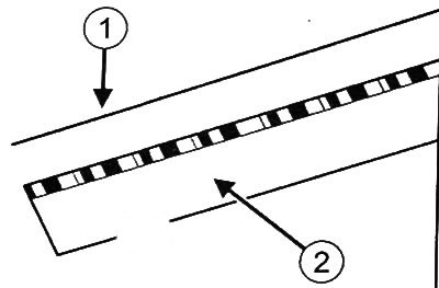
Cylinder head gasket
Measure the thickness of the cylinder head gasket (1).
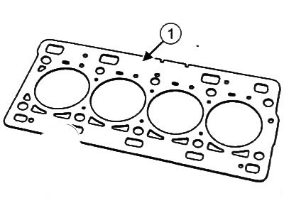
Gasket thickness (1) should be 0.49±0.04 mm.
Checking the height of the cylinder head
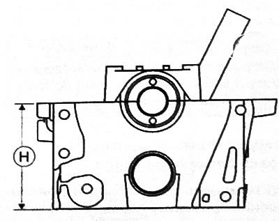
measure height (H) cylinder heads using a caliper or thickness gauge.
Height (H) cylinder head should be 9940.05 mm.
Checking the flatness of the contact surface of the cylinder head
Check the flatness of the contact surface of the cylinder head using a straightedge and a set of flat feelers or a dial gauge with bracket.
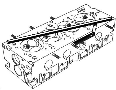
Checking surface flatness with a set of flat feelers
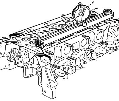
Checking surface flatness with a dial gauge
Maximum permissible deformation of the contact surface of the cylinder head: 0.05 mm.
Maximum permissible deformation of the contact surface of the cylinder block: 0.03 mm.
Attention: Regrinding of the contact surfaces of the cylinder block and block head is not allowed.
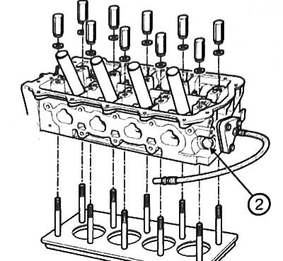
Check of tightness of a head of the block of cylinders
Using a special tool, check the tightness of the cylinder head to detect cracks.
Note: Be sure to replace the coolant temperature sensor with a bolt (2).
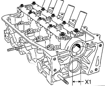
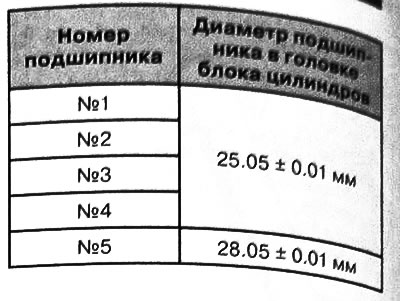
Checking the diameters of the camshaft support bearings
Using an inside micrometer, measure the diameter (X1) each cylinder head bearing.
Checking the protrusion of the valve guides
Using a vernier caliper, measure the protrusion of the valve guides (L), and also using a micrometer-caliper to measure the internal diameters of the valve guides.
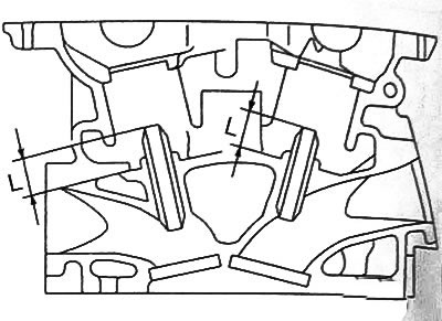
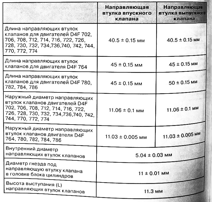
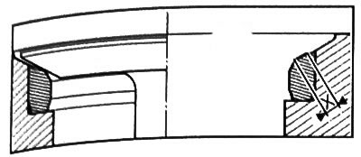
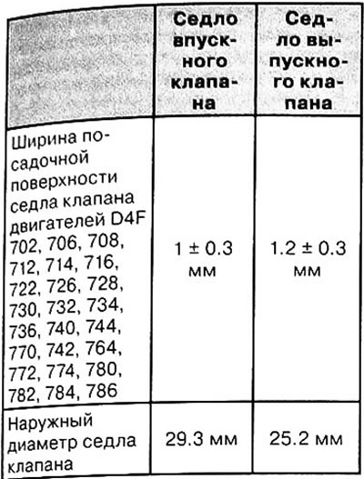
Checking the width of the seating surface of the valve seats
Measure the width of the seating surface of the valve seats (X)
Checking valves
1. Remove the cylinder head from the engine.
2. Remove the valves from the cylinder head.
3. Clean the valves with a cleaning agent and then dry with compressed air.
4. Check that the valves are not scratched or show signs of impact or abnormal wear. If any defects are found, replace the valve with a new one.
5. Verify that the valves move freely in the guide bushings.
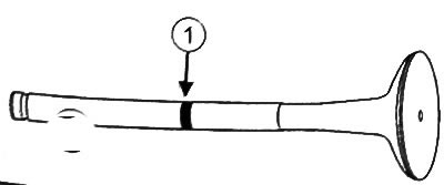
Note: When replacing valves, always ensure that the part number of the new valve is correct to avoid damaging the valves/valve seats (1) matched the old part number.
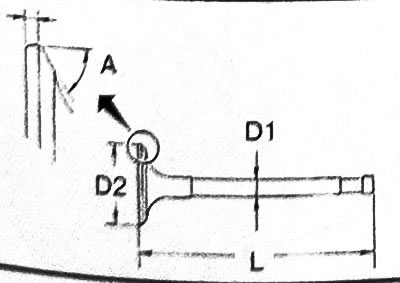
6. Using a micrometer or caliper, measure the diameter (D1) valve stem, valve length (L) and valve head diameter (D2).
7. Check clearance between valve stem and guide bushing:
Note:
The clearance between the valve stem and the guide sleeve can be measured in two ways.
The clearance between the valve stem and the guide sleeve must be:
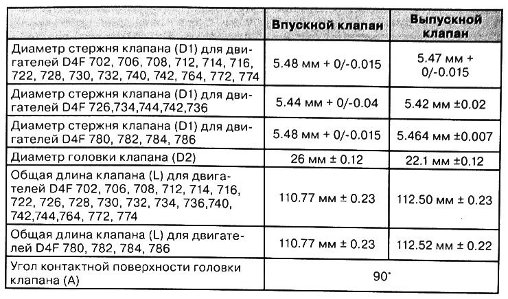
- for intake valve: 0.020 ~ 0.053mm
- for exhaust valve: 0.030 ~ 0.063mm
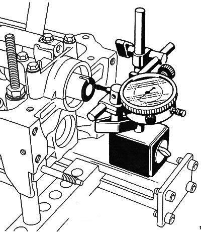
Measuring the Gap between the Valve Stem and the Guide Using a Dial Gauge
- Place the valve head at a distance (H) 25 mm from the valve seat.
- Install dial gauge with support.
- Place the dial indicator probe against the valve head, perpendicular to the camshaft axis.
- Press the valve head in the direction of the dial indicator.
- Reset the dial indicator.
- Press the valve head away from the dial indicator.
- Read the value from the dial indicator.
- Calculate the actual clearance between the valve stem and guide by dividing the value obtained from the dial gauge in half.
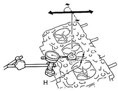
Measuring the gap between the valve stem and the guide sleeve using a micrometer and an inside gauge
- Measure the inside diameter with a caliper (2) valve guide.
- Measure the diameter of the valve stem with a micrometer (3).
- Calculate the actual clearance value by subtracting from the inside diameter of the guide bush (2) valve stem diameter (3) and divided in half.
8. Using a dial gauge, measure the maximum valve opening height. This value should be:
- exhaust valve: 8.850 mm
- intake valve: 8.849 mm.
9. Remove the valve springs from the cylinder head and check the parameters of the valve springs:
Note: The springs for the intake and exhaust valves are identical.
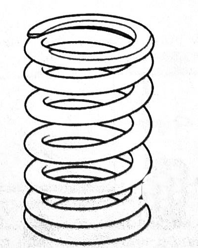
- Measure the height of the valve spring without load.
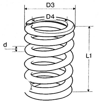
- Using a micrometer or caliper, measure the valve spring coil diameter, valve spring inner diameter, and valve spring outer diameter.
| Valve spring free height (L1) | 42.9 mm±1 |
| Compressed spring height | Not more than 25.67 mm |
| Spring coil diameter (d) | 3 mm±0.02 mm |
| Valve spring inner diameter (D4) | 14.1 mm±0.02 mm |
| Valve spring outside diameter (D3) | Not more than 20.6 mm |
- Using a special stand, check the wear of the springs by measuring the height of the spring (X1) under various loads.
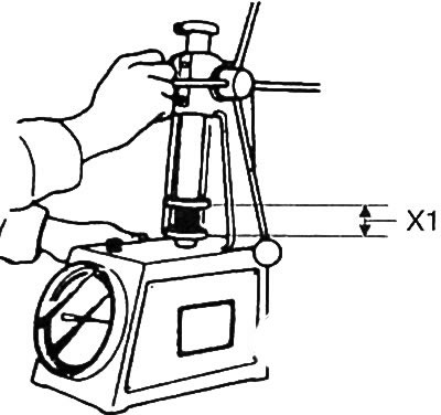
| Load, N | Spring height (XI) under load |
| 156±11 | 36 mm |
| 420±21 | 27.15 mm |
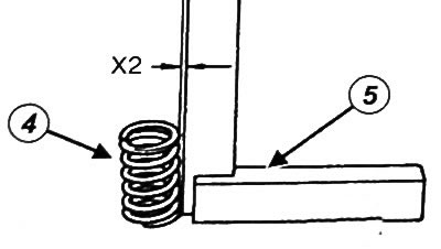
- Remove the spring from the test stand and measure the deflection of the spring (4) from perpendicularity (X2) using a square (5). Meaning (X2) should not exceed 1.4 mm.
10. After installing the valves on the cylinder head, adjust the valve clearances (see relevant section in this chapter).
Checking the camshaft
1. Remove the camshaft from the engine.
2. Clean the camshaft with cleaning agent and dry with compressed air.
3. Check that the camshaft is free of scratches, impact marks, or abnormal wear. If any defects are found, replace the camshaft with a new one.
4. Check the radial play of the camshaft.
- Remove oil from the camshaft mounting holes in the cylinder head and from the camshaft bearing caps.
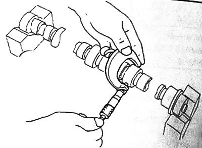
- Cut off a piece of round probe (1), equal in length to the width of the camshaft journal.
- Place a piece of feeler gauge parallel to the camshaft axis on the camshaft bearing journal.
Note: Do not rotate the camshaft during the check, otherwise the measurement accuracy will be affected.
- Install the camshaft to the cylinder head.
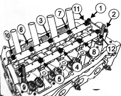
- Install the camshaft bearing caps, rocker shaft and camshaft bearing cap bolts.
- Tighten the camshaft bearing cap bolts (1) And (2) torque 9 Nm.
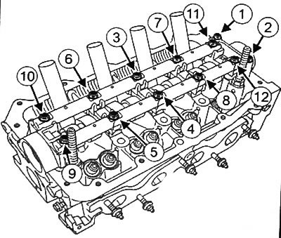
- Screw on the bolts with (3) By (12) torque 3 Nm.
- Loosen the bolt (3) camshaft bearing caps.
- Tighten the bolt again (3) torque 5 Nm.
- Repeat the above procedure for the bolts with (4) By (12).
- Loosen the camshaft bearing cap bolts and remove the rocker shaft, bearing caps and camshaft.
- Measure the width of the most flattened part of the round probe using the scale on the package of the round probe (2). The gap value should be 0.05-0.09 mm.
- Remove any remaining feeler gauge from the camshaft and bearing caps.
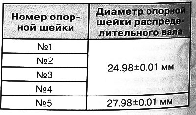
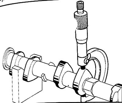
5. Measure the diameter of the camshaft bearing journals:
- Place the camshaft on the V-blocks.
Note: The #1 camshaft bearing journal is on the flywheel side.
- Measure the diameter of each camshaft bearing journal with a micrometer.
6. Check the ovality of the camshaft bearing journals:
- Place the camshaft on the V-blocks.
- Install dial indicator (5) with support (4).
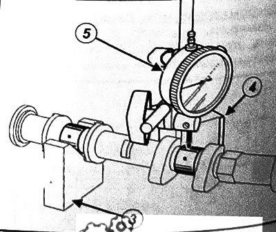
- Install the dial indicator gauge against the center of the camshaft bearing journal surface.
- Reset the watch body indicator.
- By rotating the camshaft and making sure that the dipstick does not fall into the oil holes, check the ovality of the bearing journal, the value of which should not exceed 0.05 mm.
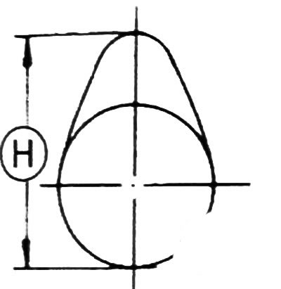
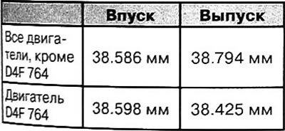
7. Check the height of the camshaft cams:
- Place the camshaft with bearing journals #2 and #4 on the V-blocks.
- Measure the height of the camshaft cams with a micrometer (H).
8. Check the axial play of the camshaft:
- Install the distributor in the cylinder head.
- Install the camshaft bearing caps, the ko-/bald shaft and the camshaft bearing cap bolts.
- Tighten the bearing cap bolts (1) And (2) torque 9 Nm.
- Screw on the bolts with (3) By (12) torque 3 Nm.
- Loosen the bolt (3) camshaft bearing caps.
- Tighten the bolt again (3) torque 5 Nm.
- Repeat the above procedure for the bolts with (4) By (12).
- Place the dial indicator probe against the end of the camshaft.
- Move the camshaft towards the dial gauge until it stops.
- Reset the dial indicator.
- Move the camshaft to the stop in the opposite direction.
- Read off the end play from a dial gauge. It should be in the range of 0.08-0.178 mm.