
Dismantling of the block of cylinders
1. Remove the power unit assembly (engine with gearbox) from the car.
2. Disconnect the gearbox from the engine (see chapter "Transmission").
3. Remove the attachment drive belt.
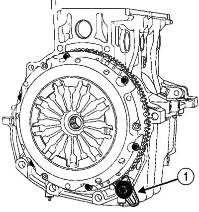
4. Install flywheel locking tool (Mot. 582-01) (1) to the cylinder block.
5. Remove the attachment drive pulley from the crankshaft.
6. Remove clutch discs (see chapter "Clutch").
7. Remove flywheel (see chapter "Clutch").
8. Remove flywheel locking tool (Mot. 582-01).
9. Place the engine on the assembly stand.
10. Drain the engine oil from the engine.
11. Remove the timing belt.
12. Remove the crankshaft seal from the timing drive side (see related section below).
13. Remove the water pump (see chapter "Cooling system").
14. Remove the air filter unit.
15. Remove generator (see chapter "Engine electrical equipment").
16. Remove the air conditioning compressor (see relevant section earlier in this chapter).
17. Remove the exhaust manifold.
18. Remove rocker cover (see relevant section earlier in this chapter).
19. Remove the cylinder head (see relevant section earlier in this chapter).
20. Remove the oil filter (see chapter "Lubrication system").
21. Remove the multifunction support (see relevant section earlier in this chapter).
22. Remove the dipstick guide tube.
23. Remove the crankshaft seal from the flywheel (see related section below).
24. Remove the oil pan from the engine (see chapter "Lubrication system").
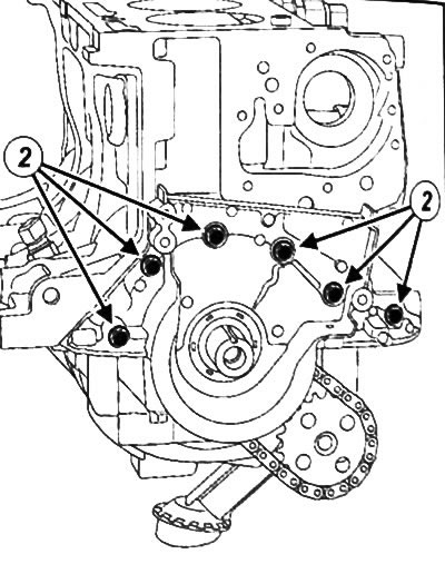
25. Remove the mounting bolts (2) and remove the crankshaft end panel.
26. Remove the oil pump with the drive chain and drive sprocket (see chapter "Lubrication system").
27. Remove pistons with connecting rods (see relevant section earlier in this chapter).
28. Remove the crankshaft (see above).
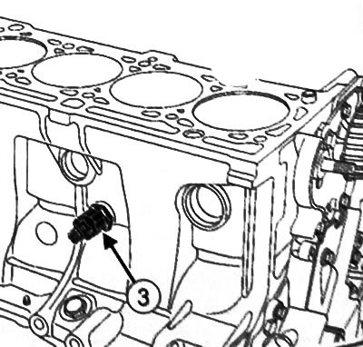
29. Unscrew the knock sensor (3).
30. Remove the water pump inlet.
31. Remove the oil pressure sensor.
Cylinder block cleaning
Attention:
- Do not scratch the connecting aluminum surfaces, any damage to the contact surfaces may cause leakage.
- Use safety goggles with side protection and sealed gloves (nitrile type).
- Do not allow cleaning agent to come into contact with paint surfaces.
- Thoroughly clean the cylinder block to prevent foreign bodies from entering the oil lines. Failure to do so may result in clogged oil lines, resulting in engine damage.
1. Disassemble the cylinder block.
2. Clean the contact surfaces of the cylinder block with a cleaning agent.
3. Remove gasket residue with a wooden or plastic spatula.
4. In addition, process the contact surfaces with fine-grained sandpaper.
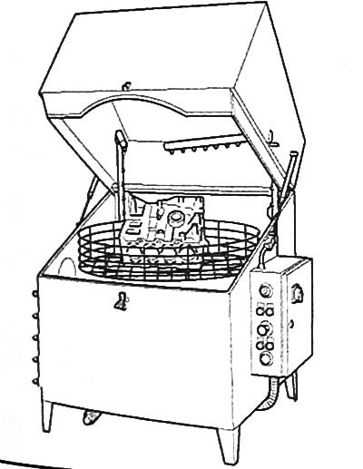
5. Wash the cylinder block using a special washer or flushing station.
Checking the block of cylinders
1. Remove the engine with gearbox assembly from the vehicle.
2. Place the engine on the assembly stand.
3. Disassemble the cylinder block (see above).
4. Thoroughly clean the cylinder block.
5. Check that the cylinder block has no scratches, impact marks, or uneven wear on the cylinders, contact surfaces, and main bearing housings. If any defects are found, replace the cylinder block with a new one.
6. Determine the size groups of cylinder bores.
Note: It is necessary to comply with the repair groups of pistons and cylinder bores.
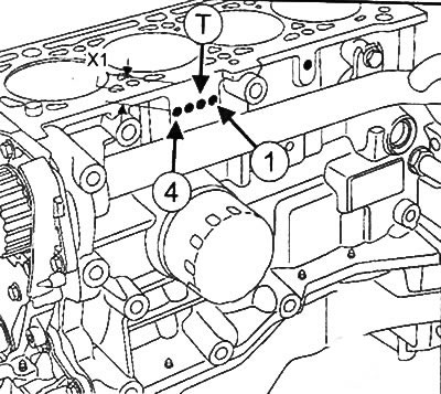
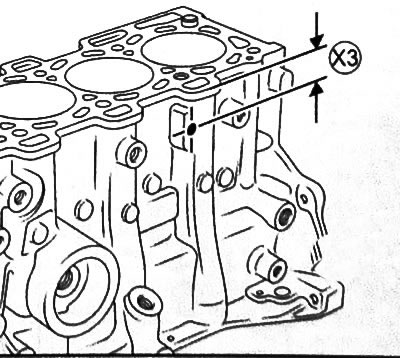
Cylinder block identification marks:Position (X1) holes (T) relative to the upper contact surface of the cylinder block corresponds to the diameter of the cylinder bores. Label (1) corresponds to cylinder No. 1, and the label (4) - cylinder number 4.
| Hole position | Size group | Cylinder bore diameter |
| X1 = 17 mm | A | 79.50 mm |
| X1 = 27 mm | IN | 79.51 ~ 79.52mm |
| X1 = 37 mm | WITH | 79.52~ 79.53mm |
7. Dimensional group of seats of main bearings in the block of cylinders (X2) marked with a hole (T) above the oil filter.
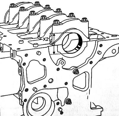
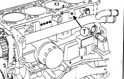
| Hole position (T) | Size group | Diameter of the main bearing seat in the cylinder block (X2) |
| (x3) = 17 mm | 1 | 51.936-51.942 mm |
| (x3) = 27 mm | 2 | 51.942-51.949 mm |
8. Using a straight edge (2) with dial indicator (3) assembly or a conventional straight edge and a set of flat feelers, determine the deformation of the contact surface of the cylinder block. Maximum permissible deformation: no more than 0.03 mm.
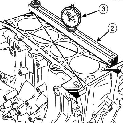
Attention: Boring of the contact surface of the cylinder block is not allowed.
9. Install the crankshaft main bearing caps by placing the #1 cap on the flywheel side.
10. Tighten the old main bearing cap bolts to 25 Nm, then tighten them another 47°±5°.
11. Measure distance (HZ) to determine the size group of the seats of the main bearings in the cylinder block.
12. Using a bore gauge, measure the diameter (X2) main bearing housing in the cylinder block.
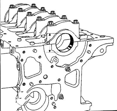
13. Compare measurement results:
- If (x3) =17 mm, diameter (X2) the bearing seat in the cylinder block should be 51.936-51.941 mm.
- If (x3) =27 mm, diameter (X2) the bearing seat in the cylinder block should be 51.942-51.949 mm.
Cylinder block assembly
Attention:
Gasket surfaces must be clean, dry and free from grease (prevent fingerprints).
Excess applied sealant may be squeezed out when tightening threaded connections. Sealant entering the coolant may cause damage to some components (engine, radiator, etc.).
Be sure to replace with new ones after each removal:
- flywheel bolts,
- water pump gasket
- water pump inlet gasket
- crankshaft seals,
- oil intake gasket (if installed),
- oil pressure line gasket,
- oil filter,
- gasket for the engine oil drain plug.
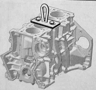
1. Place the mounting eye (Mot. 923) on the engine block as shown.
2. Remove the cylinder block from the assembly stand.
3. Clean the engine block (see above).
4. Install the cylinder block on the assembly stand using a garage winch.
5. Assembly is carried out in the reverse order of removal (see the relevant sections on installing individual components in this chapter).