
Removing
1. Place the vehicle on a two post lift.
2. Disconnect the battery.
3. Remove:
- right front wheel
- accessory drive belt,
- crankcase protection.
4. Drain the liquid from the engine cooling system.
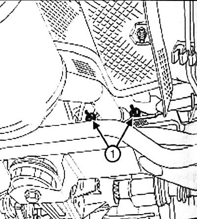
5. Remove:
- nuts (1) fixing the flange of the outlet pipeline,
- intake silencer,
- air filter housing,
- throttle block.
6. Disconnect the upstream oxygen sensor connector.
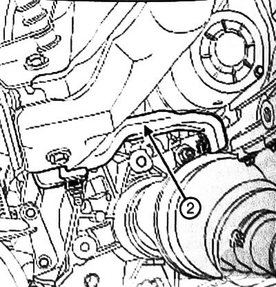
7. Remove brace (2) between the exhaust manifold and the cylinder block.
8. Install a support bar to support the engine (Mol 1672).
9. Remove:
- adaptation (Mot. 1453),
- intake manifold,
- right pendulum suspension support,
- ignition coils,
- fuel rail.
10. Disconnect:
- block of wires of the gauge of temperature of a cooling liquid,
- cooling system hoses from the thermostat housing.
11. Set aside the wiring harness.
12. Remove:
- the oil dipstick tube mounting bolt on the lifting lug on the flywheel side of the engine,
- engine lifting eye on the flywheel side,
- cylinder head cover,
- intake and exhaust camshafts.
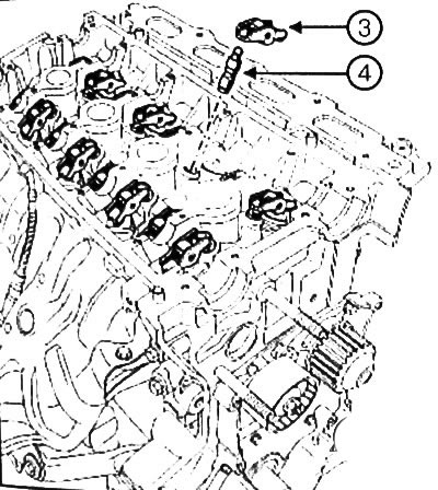
13. Remove:
- rockers (3),
- hydraulic pushers (4)
Note: Be sure to put the hydraulic tappets in a vertical position to prevent oil leakage from them.
14. Take off:
- cylinder head bolts
- cylinder head.
15. Adopt head on stand (Mol. 1573).
16. Remove the cylinder head gasket from the cylinder block.
Attention:
- 1. Wear rubber gloves to perform the operation.
- 2. When performing the operation, wear safety goggles with side pads.
- 3. Do not scratch the mating surfaces of the aluminum parts, any damage to these surfaces may cause leakage.
- 4. Do not allow cleaning agent to come into contact with paintwork.
- 5. Thoroughly clean the cylinder head so that no particles get into the oil outlet and inlet channels.
If this requirement is not observed, the oil supply channels may become clogged, which will lead to a quick failure of the engine.
1. Clean the mating surfaces with «DECAPJOINT» to dissolve adhering gasket residues.
2. Apply the composition to the surface to be cleaned, wait for about ten minutes, then remove it with a wooden spatula.
3. Use a feeler gauge to check the flatness of the mating surface.
4. The maximum allowable flatness, no more than 0.05 mm.
5. Check the cylinder head for cracks using «High pressure test stand when starting the engine».
6. Set the pistons at half stroke to prevent the pistons from touching the valves when installing the camshafts.
7. Be sure to degrease:
- mating plane of the cylinder head,
- mating plane of the cylinder block.
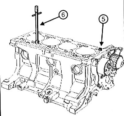
8. Check the presence of the mounting sleeve (5) on the cylinder block.
9. Install the tool on the cylinder block (Mot. 104) (6).
10. Install a new cylinder head gasket.
11. Install the cylinder head.
Attention:
- 1. Bolts can be reused if their head length does not exceed 117.7 mm (if it is larger, all bolts should be replaced).
- 2. To ensure proper tightening of the bolts, it is necessary to remove the oil with a syringe, which may be in the threaded holes of the cylinder head.
- 3. Do not lubricate new bolts. Be sure to oil the reusable bolts.
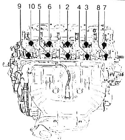
12. Tighten the cylinder head bolts in the specified order to the required torque (20 Nm).
13. Make sure that all cylinder head bolts are tightened to 20 Nm.
14. Tighten the cylinder head bolts in the specified order to the required angle (240°± 6°).
Attention: After performing this procedure, it is not necessary to tighten the cylinder head bolts.
15. Connect:
- coolant hoses to thermostat housing using tool (Mot. 1202-01) or fixtures (Mot. 1202-02), or fixtures (Mot. 1448),
- coolant temperature sensor connector.
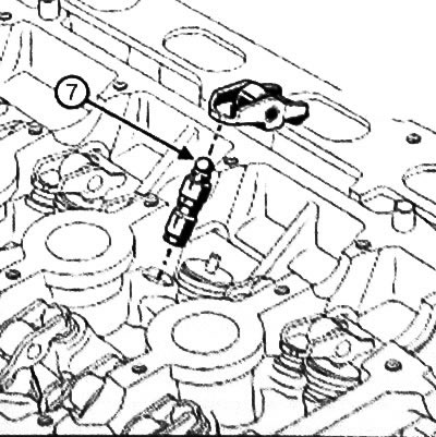
16. Refill the hydraulic tappets, because the hydraulic fluid from the tappets may leak if they are not operated for a long time.
17. To make sure that refueling is necessary, press on the top of the pusher (7) thumb.
18. If the pusher plunger is recessed:
- immerse the tappets in a container with diesel fuel,
- then install pushers.
19. Install rocker arms.
Camshaft identification
Inlet camshaft
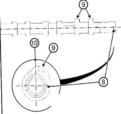
20. Position the groove (8) at the end of the camshaft horizontally and below the axis of the shaft.
21. Cams (9) cylinder number 1 should be located to the right of the vertical axis (10), when viewed from the flywheel side.
Exhaust camshaft
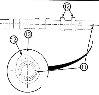
22. Position the groove (11) at the end of the camshaft horizontally and below the axis of the shaft.
23. Cams (12) cylinder number 1 should be located to the left of the vertical axis (13), when viewed from the flywheel side.
24. Install:
- camshafts, lubricating the bearing journals with engine oil,
- cylinder head cover,
- flywheel side engine lifting eye.
25. Torque tighten the lifting eye bolts on the flywheel side (11 Nm).
26.Install:
- oil dipstick tube fixing bolt on the lifting eye,
- fuel rail,
- right pendulum suspension support,
- intake manifold.
27. Connect the upstream oxygen sensor connector.
28.Install:
- throttle block,
- air filter housing,
- intake silencer,
- brace between exhaust manifold and
29. Tighten in the order shown to the required torque:
- strut-to-cylinder block bolt (21 Nm),
- strut nut to exhaust manifold (21 Nm).
30.Install:
- nuts of fastening of a flange of a reception pipe of the final pipeline,
- engine undertray protection.
31. Install fixture (Mot. 1453).
32.Remove the support bar to support the engine (Mot. 1672).
33.Install:
- timing belt,
- accessory drive belt.
Note:
- If any stud came out during this operation, apply to its thread «High strength locking compound».
- Torque tighten exhaust manifold mounting studs (8 Nm).
34. Torque tighten the nuts of the studs securing the catalytic converter to the exhaust manifold (21 Nm).
35. Fill the engine cooling system with liquid.
36.Install the right front wheel.
37. Connect the battery.
38. Remove air from the cooling system.