
Removal and installation, K7M engine (8 valves)
Removing
1. Disconnect the battery.
2. Disconnect:
- air filter housing,
- ignition coil unit
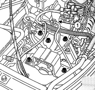
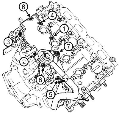
3. Disconnect the EVAP tube from the holder at the point (1).
4. Disconnect the crankcase ventilation hose (2).
5. To turn away bolts of fastening of a cover of a head of the block of cylinders.
6. Disconnect:
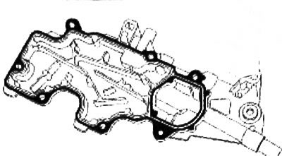
- cylinder head cover,
- cylinder head cover gasket.
Installation
Caution: Never clean the mating surfaces of light-alloy parts with sharp-edged tools.
1. Clean the mating surface of the cylinder head cover.
2. Install the cylinder head cover with a new gasket.
3. Pre-torque tighten the cylinder head cover bolts in the order shown (2 Nm).
4. Tighten the cylinder head cover bolts in the specified order to the required torque (10 Nm).
5. Connect the crankcase ventilation hose.
6. To attach to the holder a tube of system of catching of vapors of gasoline.
7. Install:
- ignition coil block
- air filter housing.
8. Connect the battery.
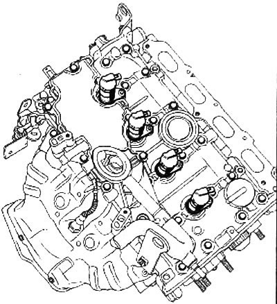
Removal and installation, K4M engine (16 valves)
Removing
1. Place the vehicle on a two post lift.
2. Disconnect the battery.
3. Disconnect:
- right front wheel.
- accessory drive belt,
- timing belt,
- intake silencer,
- air filter housing,
- throttle block,
- intake manifold.
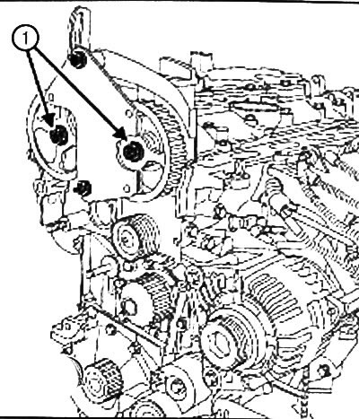
4. Install fixture (Mot. 1490-01) on the camshaft pulleys.
5. Disconnect:
- fastening nuts (1) camshaft pulleys,
- adaptation (Mot. 1490-01),
- and camshaft pulleys.
6. Remove ignition coils.
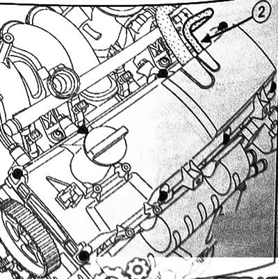
7. Disconnect:
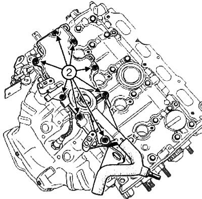
- the lifting eye bolt on the flywheel side of the cylinder head cover,
- fastening bolts (2) oil separator,
- oil separator.
8. To turn away bolts of fastening of a cover of a head of the block of cylinders.
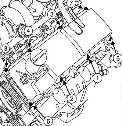
9. Vertically separate the cylinder head cover by tapping on the lugs (3) bronze punch.
10. Remove the cylinder head cover.
Installation
Attention:
- 1. Never clean the mating surfaces of light-alloy parts with sharp-edged tools.
- 2. Wear safety goggles.
- 3. This operation must be carried out with protective gloves.
- 4. Do not allow cleaning agent to come into contact with paintwork.
- 5. Thoroughly clean the cylinder head so that no particles get into the oil outlet and inlet channels.
If this requirement is not observed, the oil supply channels may be clogged, which will eventually lead to a quick failure of the engine.
1. Clean the mating surfaces of the cylinder head cover with «DECAPJOINT» to dissolve adhering gasket residues.
2. Apply the composition to the surface to be cleaned, wait for about fifteen minutes, then remove it with a wooden spatula.
Note: The mating surfaces of the cylinder head cover must be clean, dry and free of oil (avoid touching them with your fingers).
3. Lubricate the camshaft bearings in the cylinder head with engine oil.
Attention:
- 1. Do not apply oil to the upper mating surface of the cylinder head.
- 2. Applying too much sealant may cause sealant to be squeezed out when parts are tightened. A mixture of sealant and liquid can cause failure of some components and assemblies (engine, radiator, etc.).
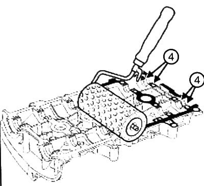
4. Apply with a roller (for painting works) compound «COLLE RESINE» onto the mating surface until it turns reddish in color.
5. Remove a piece of fabric composition «COLLE RESINE», on work surfaces (4) six bearings in the cylinder head cover.
6. Install the cylinder head cover.
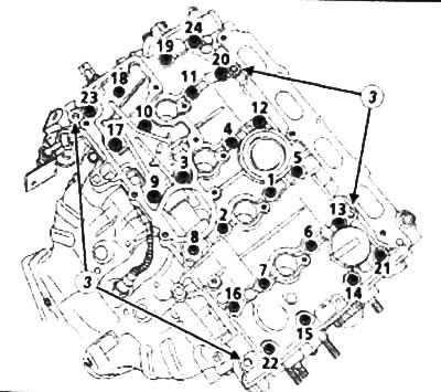
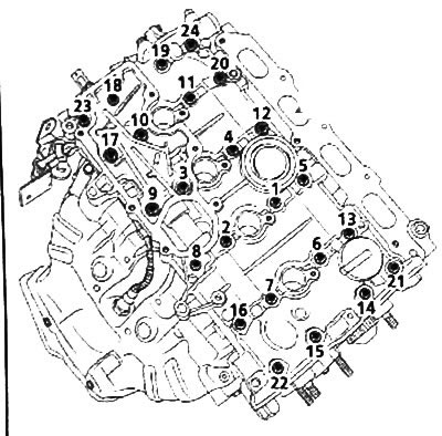
7. Tighten in order to the required torque:
- bolts of fastening 22, 23, 20, 13 of a cover of a head of cylinders (8 Nm),
- mounting bolts 1 - 12, 14 -19, 21 - 24 cylinder head covers (14.5 Nm).
8. Loosen bolts 22, 23, 20, 13 in the specified order.
9. Tighten bolts 22, 23, 20, 13 of the cylinder head cover in the specified order to the required torque (14.5 N·m).
Note: The mating surfaces of the cylinder head cover must be clean, dry and free of oil (avoid touching them with your fingers).
Caution: Applying too much sealant can cause sealant to be squeezed out when parts are tightened. A mixture of sealant and liquid can cause failure of some components and assemblies (engine, radiator, etc.).
10. Apply with a roller (for painting works) compound «COLLE RESINE» onto the mating surface until it turns reddish in color.
11. Install the oil separator.
12. Tighten the oil separator mounting bolts in the specified order to the required torque (10 N·m).
13. Screw in the lifting eye bolt on the flywheel side of the cylinder head cover.,
14. Torque tighten the lifting eye bolt on the flywheel side (11 N·m).
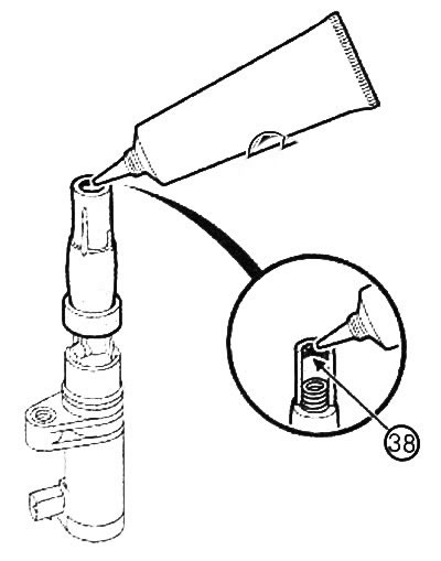
15. Bead all four ignition coils (38) «FLUORINE LUBRICANT» (Stock Ns 82 00168 855) 2 mm in diameter around the inner circumference of the high voltage wire cap.
16. Install:
- intake manifold,
- throttle block,
- air filter housing,
- intake silencer,
- timing belt,
- accessory drive belt,
- right front wheel
17. Connect the battery.