
Cylinder head height, mm: H = 159.5±0.2.
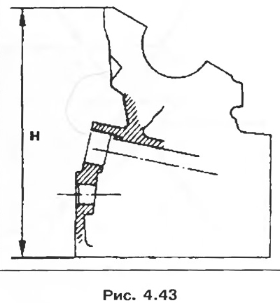
The maximum allowable deformation of the mating surface, mm: 0.05.
2. Valve guides.
Inner diameter, mm: 8.
Outer diameter of the guide sleeve, mm:
- nominal: 13;
- repair: 13.30.
Attention! The intake and exhaust valve guides have valve stem seals that must be replaced each time the valve train is disassembled.
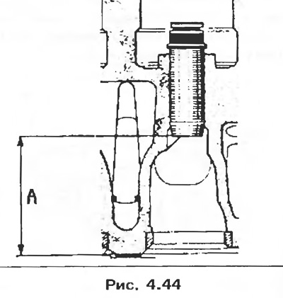
The position of the guide bushings of the intake and exhaust valves relative to the lower mating surface of the cylinder head, mm: A = 43.25.
3. Valve springs.
Free length, mm: 43.41
Loaded length:
- 230±20 N = 37.9 mm;
- 705±35 N = 28.4 mm.
The length of the spring at full compression of the coils, mm: 25.77.
Wire diameter, mm: 4.25.
Inner diameter, mm: 21.5±0.1.
4. Valves.
Rod diameter, mm: 8
Chamfer Angle:
- intake valve: 120°;
- outlet valve: 90°.
Head diameter, mm:
- intake valve: 36.1;
- exhaust valve: 31.5.
Attention! When replacing valves, the new valves installed must have the same part number as the previous valves to prevent damage to the valves and seats.
The same part number can have multiple markings, in which case all valves are fully interchangeable.
Verify that new valves with different markings from removed valves have the same part number.
5. Valve seats.
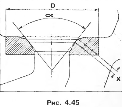
Seat outer diameter D, mm:
- inlet valves. 37 (37,3);
- exhaust valves. 32.6 (32,89).
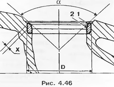
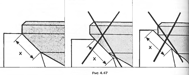
Inlet valves X = 1.8; α= 120°.
Seat face 1 is ground with a 30°cutter, reduce the width of the face by grinding face 2 with a 60°cutter until width X is obtained.
Exhaust valves X = 1.8; α= 90°.
Seat face 1 is ground with a 45°cutter, reduce the bevel width by grinding bevel 2 with a 75°cutter until width X is obtained.
Attention! Check the correct fit of the valve to its seat (pic. 4.47).
6. Camshaft:
- axial clearance, mm: 0.05-0.13;
- number of bearings: 5.
7. Pistons.
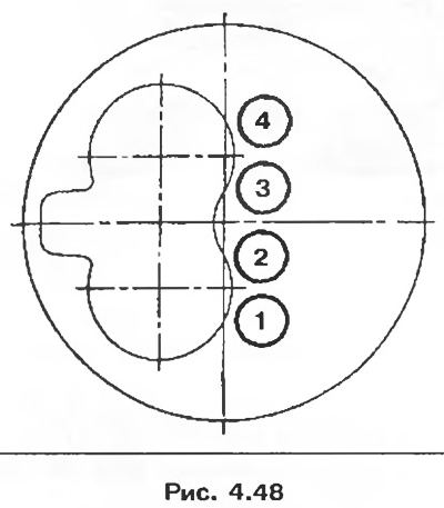
Mark 1 indicates the depth of the recess in the piston crown.
Mark 2 indicates the type of engine 8Q piston A-B-C.
Mark 3 indicates the piston size group of the piston.
Label 4 is for the supplier.
Selection of pistons for cylinder liners
Table 4.2
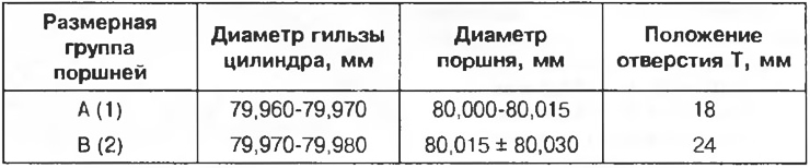
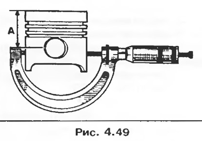
The piston diameter should be measured at a distance of A = 60 mm.
8. Cylinder liners.
Attention! Observe the selection of the diameters of the pistons and cylinder liners. The selection is determined by the position of the holes T in relation to the mating surface of the cylinder head. The position of these holes makes it possible to select the tolerances of the cylinder liners in their nominal size group and therefore the piston diameters corresponding to these tolerances (table 4.2).
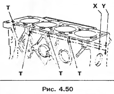
Note. The marking holds: 1 and 2 - designation of the sizes of the group of pistons A or B; T - the position of the holes indicates the size group for the cylinder: X = 18 mm, Y = 24 mm.
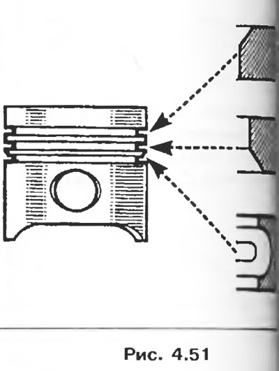
9. Piston rings.
Thickness, mm:
- top compression ring.
- lower compression ring.
- oil ring 3.
Piston ring locks are set through 120°. Compression rings are installed with the Tor mark up.
10. Connecting rods.
Axial clearance of the lower head of the connecting rod, mm: 0.22-0.40.
11. Crankshaft.
Number of main bearings 5.
Axial clearance, mm: 0.07-0.23.
Table 4.3
There are persistent half rings of various thicknesses, mm: 2.30-2.35-2.40-2.45.
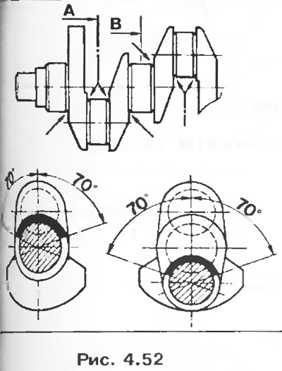
When grinding, the fillets on the plane must remain intact in the areas forming the corner (pic. 4.52, arrows).
12. Intermediate shaft.
Axial clearance, mm: 0.07-0.15.
The intermediate shaft is installed in two bushings with a diameter, mm:
- inner sleeve 39.95,
- outer sleeve 40.5.
Parts to be replaced when removed
- All seals and gaskets.
- Flywheel bolts.
- Connecting rod cap bolts.
- Crankshaft mounting bolts.
- Valve guides.
- Refractory washers for nozzles.
- Bolt of fastening of a head of the block of cylinders.
- Pipe of the cooling system.