
Required special tool
- Mot. 1040-01 Trolley for removal and installation of the power unit.
- Mot. 1159 Device for fixing the engine on the subframe.
- Mot. 1202, Mot. 1448 Pliers for flexible clamps.
- Mot. 1311-06 Tool for removing fuel lines.
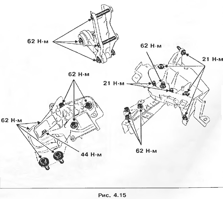
Tightening torques, Nm
- Subframe front mounting bolts: 62.
- Rear subframe bolts: 105.
- Bolts of fastening on the engine of the upper bracket of the front right support of the suspended engine suspension: 62.
- Nut of fastening of the upper front right bracket of the pendulum suspension of the engine: 44.
- Support pad mounting nut on the front left side member bracket: 62.
- Bolts of fastening of a shock-absorber rack to a rotary fist: 180.
- Floating caliper mounting bolt: 40.
- Steering shaft universal joint yoke bolt: 30.
- Wheel bolts: 90.
Removing
1. Place the vehicle on a post lift.
2. Lower the battery.
3. Drain:
- coolant from the cooling system by disconnecting the radiator outlet hose;
- oil from the gearbox and engine, if necessary.
4. Remove:
- engine hood;
- front wheels;
- connecting rod between the subframe and the body;
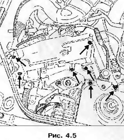
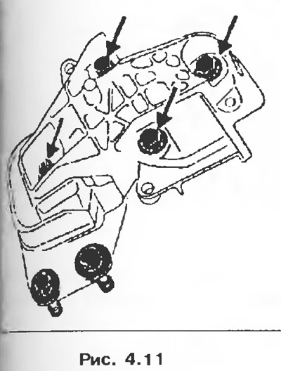
- mounting bolts 1, turn the floating brake calipers as shown in the figure and attach them to the suspension springs.
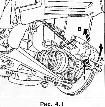 |  |
5. Remove bolts of fastening of shock-absorber racks to rotary fists.
6. Remove:
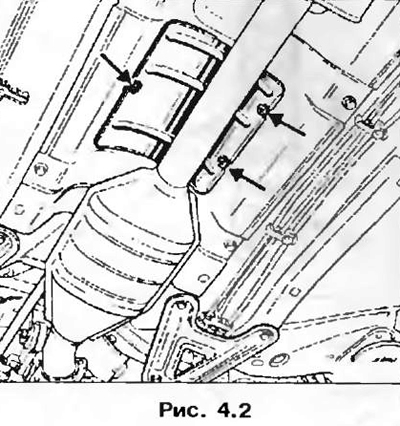
- the heat-reflecting shield of the exhaust gas system, as well as the gearshift drive rod, by disconnecting it from the gear selection lever and the gearshift lever;
- muffler intake pipe;
- mass bus on the gearbox;
- front bumper;
- air intake pipe of the air filter;
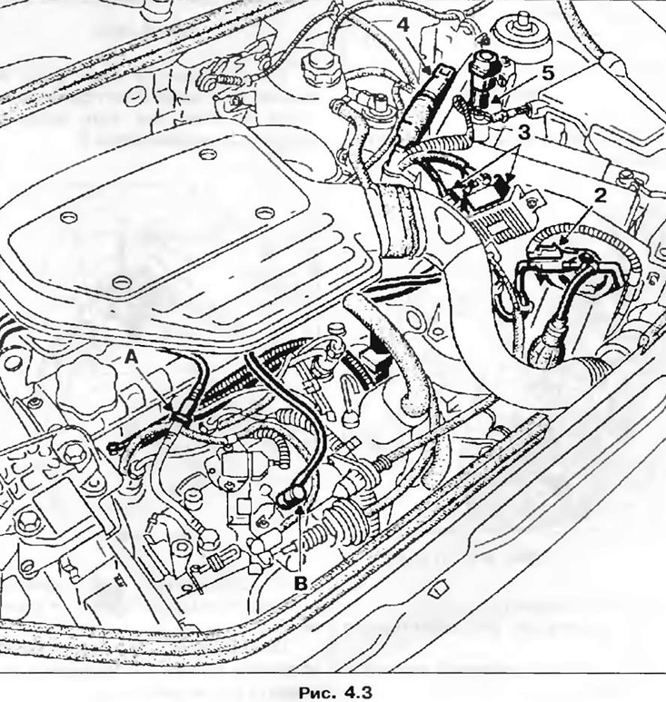
- fitting of pipelines for supply and return of fuel A and B;
- slots 2, 3, 4 and 5.
7. Disconnect the fuel hoses on the air filter housing and the timing cover, and also remove the diesel fuel filter from the bracket and take everything aside.
8. Disconnect the quick connectors (pic. 4.4).
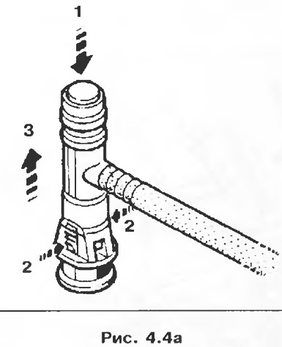 | 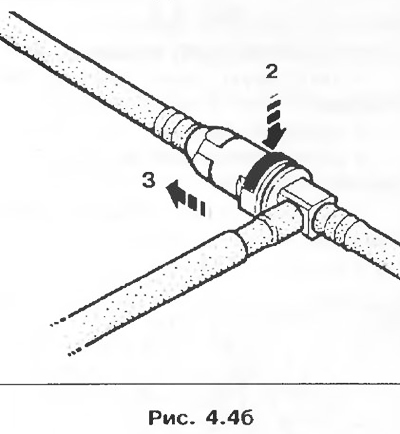 |
9. Remove the computer mounting bracket.
10. Disconnect:
- hoses from the expansion tank;
- hose from the vacuum brake booster;
- heating radiator hoses (with plastic (pic. 4.6a) or metal (4.6b) nozzles).
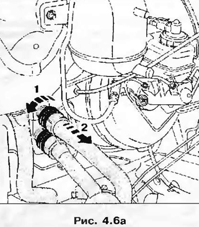 | 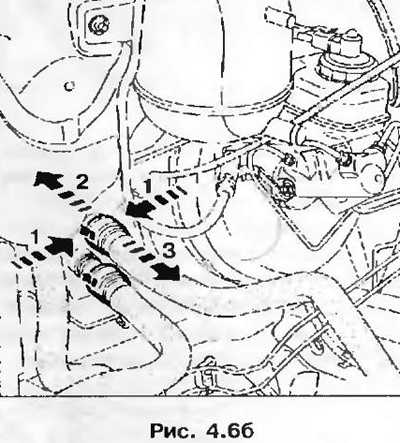 |
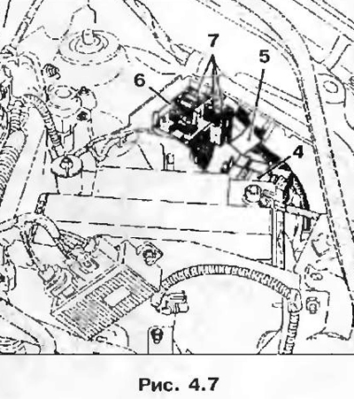
11. Disconnect the relay box 4, connector 5, as well as the fuse box 6, while removing the fuse links 7.
12. Disconnect the fuel and clutch control cables.
13. Release the power steering reservoir from the latches and place it on the engine.
14. Remove:
- top mount details! diator and fix the engine radiator;
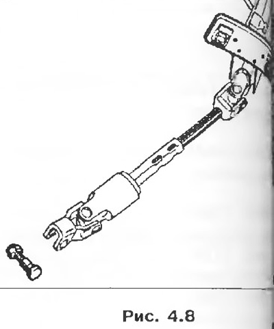
- nut and eccentric terminal connection of the steering shaft universal joint yoke after having previously displaced the protective cover.
Attention! Features of vehicles equipped with driver safety coy.
To prevent damage to the slip ring under the steering wheel, the following rules must be observed:
- before disconnecting the left column and the steering mechanism, it is necessary to block the left wheel in the straight ahead position with a special device, and the steering wheel must remain locked during the entire time of work;
- if in doubt about the correct centering of the contact, you need to remove the steering wheel and center it.
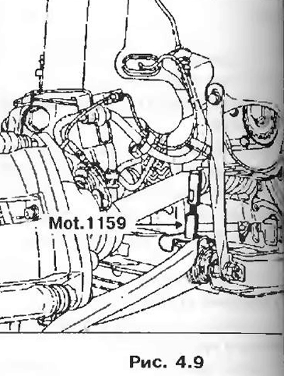
15. Install tool Mot. 1159 between subframe and cylinder block.
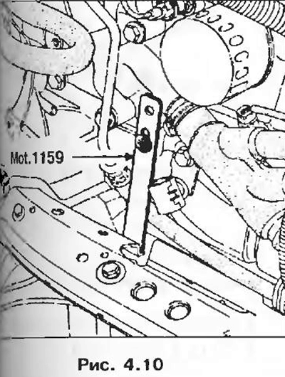
16. Install retaining clip Mot. 1159 to the place of fastening of the cooling system on the cylinder block.
17. Remove the upper engine mount bracket.
18. Install a wedge between the gearbox and subframe.
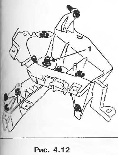
19. Remove nut 1, then use a bronze drift to knock out the pendulum support mounting pin.
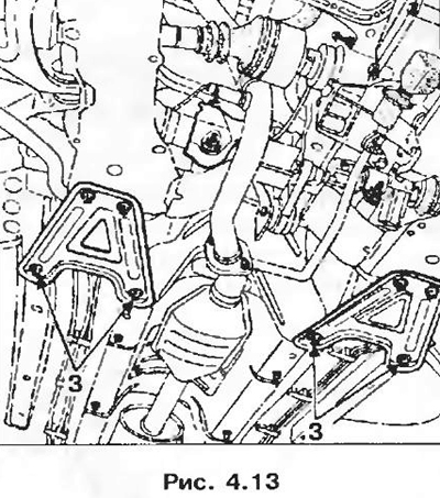
20. Remove mounting bolts 3.
21. Install trolley Mot. 1040-01 below the subframe.
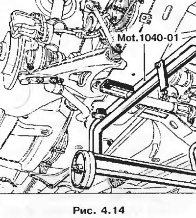
22. Lower the axle until the cart wheels are in contact with the floor.
23. Remove the subframe mounting bolts and remove the power unit by lifting the body up.
Note. If the work requires separating the parts of the power unit consisting of engine, gearbox and subframe, note the position of tool Mot. 1159 on a stretcher.
Installation
1. Alignment of the subframe with the body is made easier by inserting two threaded rods of tool Mot. 1233-01 into the front mounting holes of the subframe.
2. Tighten the screws securing the subframe to:
- 62 Nm front;
- 105 Nm rear.
3. Install in the reverse order of removal.
4. Install the heat shields correctly.
5. Install the floating caliper mounting bolts, lubricating them with Loctite FRENBLOC sealant, and tighten them to the specified torque.
6. Press the brake pedal several times to set the brake pistons to the working position.
7. Do:
- refueling gearbox and engine oil (if necessary);
- filling with coolant and removing air from the cooling system (see chapter «Maintenance»).
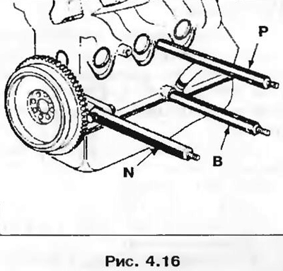
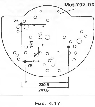
Installing the engine on the base plate
Attachment pins Mot. 995 (N, P, B) are fixed on the cylinder block so that they fit into the holes (12, 25 and 26) plates.
 |  |