
Required special tools and fixtures
- Mot. 251-01 Bracket for indicator.
- Mot. 252-01 Stand for measuring piston protrusion.
- Mot. 591-02 Magnetic base pointer for angular bolt tightening.
- Mot. 591-04 Angle wrench.
- Mot. 1054 TDC lock.
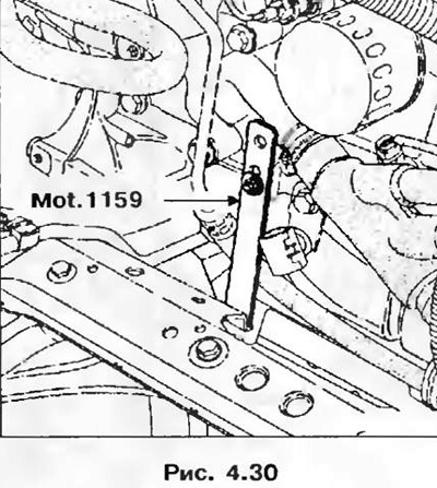
- Mot. 1159 Device for supporting the engine on the subframe.
- Mot. 1202 Pliers for flexible clamps.
- Mot. 1273 Belt tension gauge.
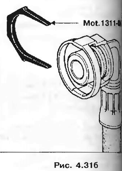
- Mot. 1311-06 Fuel line removal tool.
- Engine maintenance tool.
- Nozzle «Torx» at 55.
Tightening torques, Nm
- Nut of fastening of a tension roller: 50.
- Crankshaft pulley bolt: 20 + 115°± 15°.
- Bolt of the top bracket of the suspension bracket of the engine: 62.
- Nut of the upper bracket of the suspension support of the engine: 44.
- Wheel bolts: 90.
Removing
1. Place the vehicle on a two post lift.
2. Disconnect the battery.
3. Remove:
- engine hood;
- timing belt drive.
4. Drain the cooling system by disconnecting the outlet hose on the radiator.
5. Install tool Mot. between subframe and cylinder block. 1159
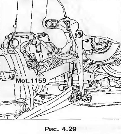
6. Fit the bracket of tool Mot. 1159 to the coolant hose mounting on the cylinder block, then remove the engine support.
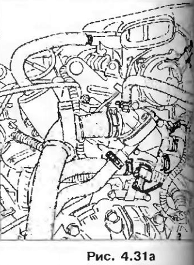
7. Remove:
- muffler intake pipe;
- hoses and sensor connectors on the thermostat housing;
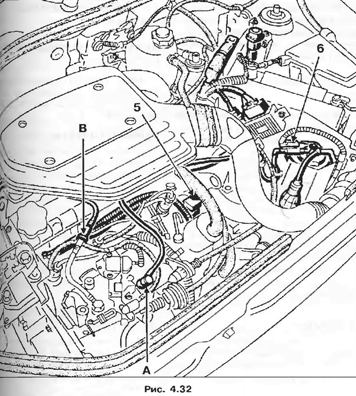
- fitting 1 with tool Mot. 1311-06.
 |  |
8. Remove:
- air filter, while disconnecting the connectors of the EGR solenoid valve and the air temperature sensor (Disconnect the fuel lines from the air filter housing.
- fuel control cable;
- power wires for glow plugs;
- 3rd cylinder injector connectors with built-in needle connector sensor, as well as connector for idle speed solenoid valve 5;
- fittings of pipelines of gas and fuel return in A and B.
9. Disconnect the connector 6 for the diesel fuel filter, disconnect the filter from the bracket, release the pipelines with the filter to the side.
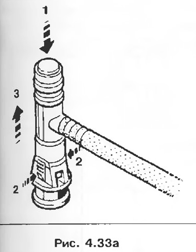
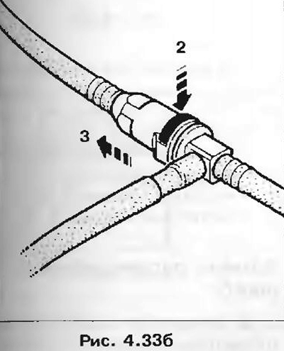
10. Disconnect the quick connectors (pic. 4.33).
 |  |
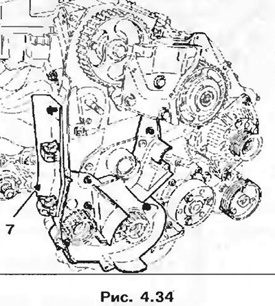
11. Remove the fuel line holder bracket 7.
12. Release bolts of fastening of the bottom cover of a drive of the gas-distributing mechanism.
13. Remove:
- accessory drive belt tensioner;
- cylinder head bolts.
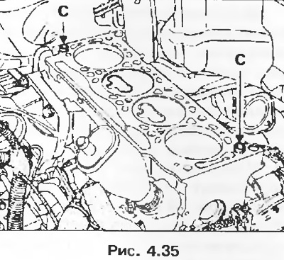
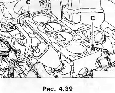
14. Separate the head of the block, moving aside the lower part of the upper cover of the gas distribution mechanism; carry out this operation without turning the block head around the vertical axis, as it is centered by two bushings C.
15. Using a syringe, remove the remaining oil from the sockets for the block head bolts. This is necessary to ensure that the bolts are properly tightened.
16. Take measures to ensure that foreign particles do not enter the oil supply channel of the cylinder head.
Attention! Failure to do so can lead to clogged oil passages and cause rapid wear of the camshaft.
Cleaning and checking
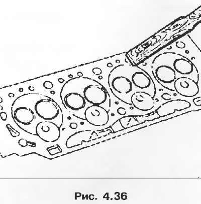
Attention! It is not allowed to clean the mating surfaces of aluminum parts with a tool with a sharp edge. Use Decapjoint to dissolve adhering gasket residue.
1. Apply the compound to the surface to be cleaned. Wait for about ten minutes, then remove any adhesive residue with a wooden spatula. This operation is recommended to be performed with gloves.
Attention! This operation must be carried out carefully to avoid the entry of foreign particles into the system of channels for supplying pressurized oil to the camshaft (channels are located in the cylinder block and cylinder head). Failure to do so may result in blockage of the rocker jets and cause rapid wear of the cams and rocker bearing surfaces.
2. Check the deformation of the mating surface. The maximum allowable flatness is 0.05 mm.
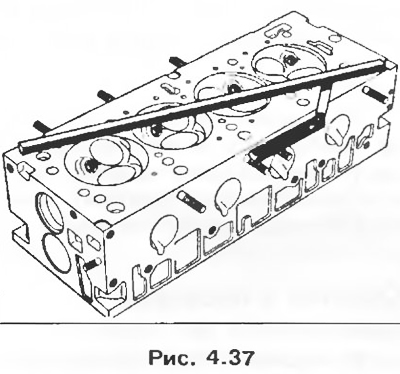
Attention! Grinding of mating surfaces of the cylinder head is not allowed.
3. Check up absence of cracks of a head of the block of cylinders.
Determination of gasket thickness
1. Remove carbon deposits from the bottom of the pistons.
2. Turn the crankshaft in the direction of rotation one revolution so that the No. 1 cylinder piston is near TDC.
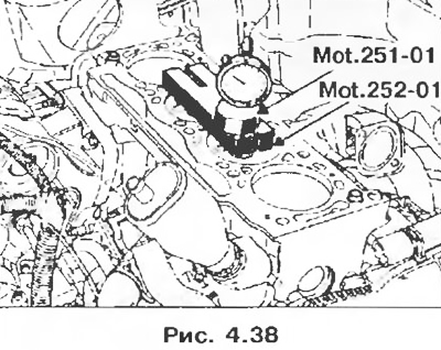
3. Place support Mot. on the piston. 252-01
Install bracket Mot. 25101 with stand indicator Mot. 252-01. Bring the indicator foot into contact with the piston crown and determine the TDC of the piston.
Attention! All measurements must be taken along the longitudinal axis of the engine to eliminate errors due to piston tilt.
4. Measure the protrusion of the pistons.
Attention! When choosing the thickness of the gasket, you should be guided by the largest amount of protrusion of the piston.
5. If the maximum protrusion of the engine piston:
- less than 0.858 mm, then a gasket with a tongue with two holes should be used;
- from 0.858 mm to 1 mm, use a gasket that has a tongue with one hole;
- more than 1 mm, use a gasket that has a tongue with three holes.
Installation
1. Install the preselected head gasket. The head of the block is centered using two bushings C.
2. Install the pistons approximately in the middle of the stroke so that they come into contact with the valves when the head bolts are tightened.
3. Center the block head on the bushings.
4. Lubricate the bottom of the heads and the threads of the bolts with oil.
5. Tighten the block head bolts (see chapter «Maintenance»).
6. Install in the reverse order of removal.
7. Install the timing belt.
8. Fill with coolant and bleed air from the cooling system (see chapter «Maintenance»).