
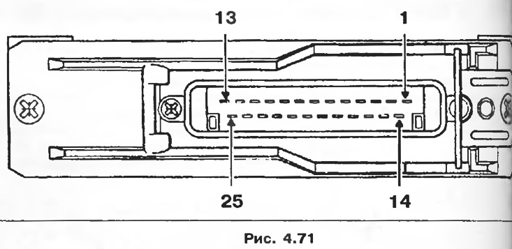
Connection
1 - Computer power.
2 - Mass of the computer.
3 - Mass of sensors.
4 - Power supply of the load potentiometer.
5 - EGR solenoid valve control.
6 - Management of the injection advance corrector.
7 - Needle lift sensor signal.
8 - Engine mode signal.
9 - Control of the warning light for the preheating system.
10 - Diagnostic line information L.
11 - Condition of the air conditioner.
12 - Vehicle speed signal.
13 - Diagnostic line information K.
14 - Preheating relay control.
15 - Corrector relay control.
16 - Fast idle control.
17 - Load lever position signal.
18 - Control of the diagnostic signal lamp.
19 - Control of turning off the air conditioner.
20 - Power steering electric pump relay control.
21 - Information about the engine speed.
22 - Not used.
23 - Load potentiometer signal.
24 - Air temperature sensor signal.
25 - Coolant texture sensor signal.
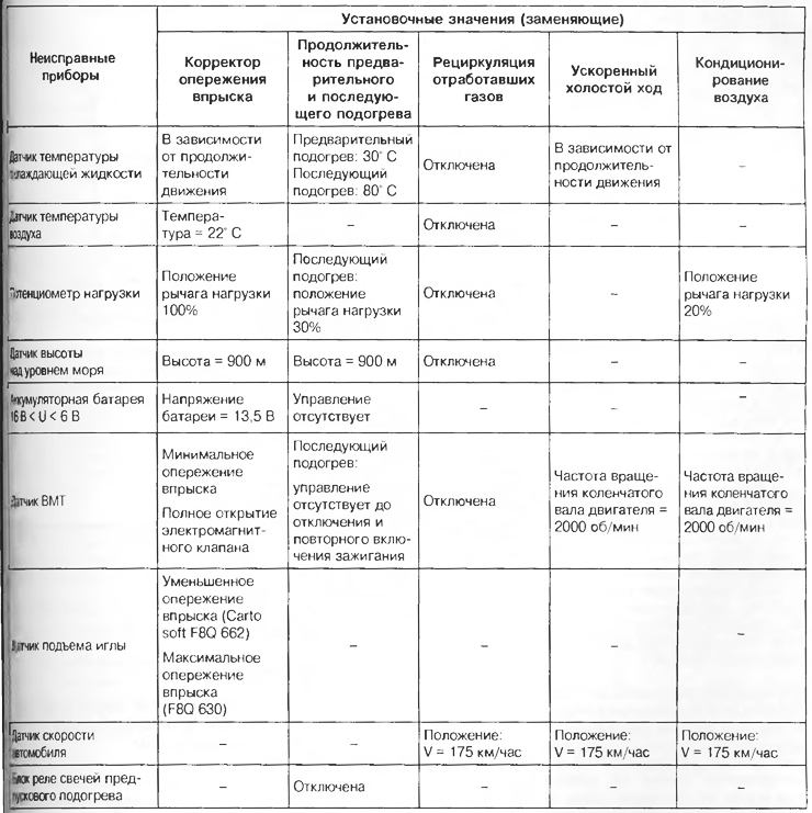
Emergency modes
If one of the following devices fails, the computer goes into emergency mode, that is, it starts using substitute values to ensure the operation of the engine.
Table 4.9
Interaction with air conditioner computer
Electrical connection:
- air conditioning computer with injection computer using a wire. This wire only transmits a signal about the operation of the controller. Based on this signal, the injection computer learns that the air conditioner is turned on: output 11;
- injection computer with air conditioning computer using a wire. This wire transmits signals to enable and disable the fall of the air conditioning compressor: terminal 19.
Compressor activation algorithm
In some engine operating modes, the injection computer inhibits the operation of the compressor.
When starting the engine
Compressor activation is blocked after starting the engine for 3 seconds.
Engine power maintenance algorithm
When the computer detects the position «pedal pressed all the way down» A/C compressor turns off for 8 seconds.
Engine stop warning
If the engine speed is below 650 rpm, the compressor is switched off. Its operation resumes when the engine speed exceeds 775 rpm.
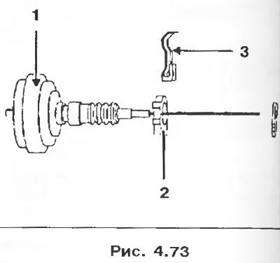
Idling and minimum feed adjustment (engine stop prevention)
These adjustments should be carried out only on a hot engine, after at least two switching on of the electric fans.
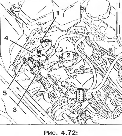
1 - Idle adjustment screw;
2 - Load lever;
3 - Minimum feed adjustment screw (engine stop prevention);
4 - Fast idle lever;
5 - Idle cable clamp.
1. Make sure the fast idle lever is in the off position.
2. Using screw 1, set the engine idle speed within 825±25 rpm.
3. Install a 4 mm spacer between the load arm 2 and the minimum feed screw 3.
4. Using the minimum feed screw 3, set the engine speed within 1250±50 rpm.
5. Remove the 4mm shim, then rev the engine twice to the limit.
6. Check idle speed; if necessary, repeat the idle speed adjustment and recheck the minimum flow adjustment.
Attention! Adjustment of idle speed and minimum fuel supply must be made with particular care, since this adjustment directly affects the operation of the engine at idle and during engine braking (engine misfires, idle recovery delays, etc.).
Fast idle
Having disconnected the vacuum tube from the pneumatic actuator, install the cable clamp 5 (pic. 4.72) at a distance of 2 + 1 mm from the fast idle lever 4.
Note: The fast idle speed is not directly adjustable on the vehicle; the adjustment is made on the slipway for servicing the devices of the injection systems.
Checking the maximum speed
When the engine is warm, press the pedal to the stop on the fuel supply control; engine speed should be between 4500 and 4700 rpm (adjustment of the maximum speed can only be carried out on the stocks of the Renault Injection Center).
Control
Fast idle is controlled by the computer through the pneumatic control solenoid valve (option with or without air conditioning).
Fast idle mode is activated:
- if, when the key is installed in the ignition switch, the temperature of the coolant is below 10°C;
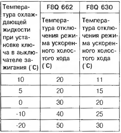
Table 4.10
- if the engine speed has dropped to 650 rpm and the vehicle speed is less than 25 km/h (to make it easier to start). The fast idle mode is disabled as soon as the engine speed is greater than 850 rpm.
Note
1. Fast idle mode enabled:
- the solenoid valve is not controlled;
- cable is loose, not tight.
2. Rated idle mode:
- a solenoid valve is controlled;
- rope is pulled.
3. As soon as the air conditioner is turned on on the control panel, the fast idle mode is immediately activated.
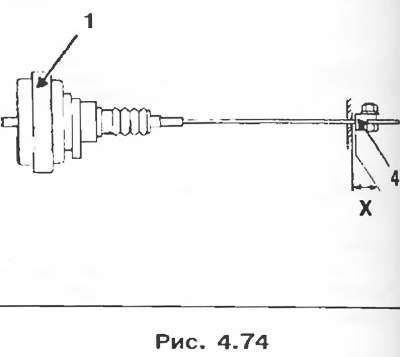
Pneumatic fast idle
1. Install the pneumatic actuator 1 on the rear protective bracket of the injection pump 2.
2. Snap the spring clip onto the air actuator.
3. Install stopper 4 on the rope.
4. Install the cable clamp so that the X dimension is 2±1 mm. Tighten the clamp nut.
Pre-heating and post-heating control
Pre-heating and post-heating are controlled by a computer. The computer controls the glow plug relay box.
1. Installing the key in the ignition switch in position «M» - Preheating
1.1. Variable preheating mode
It is determined by coolant temperature, battery voltage and altitude (computer internal sensor) when the ignition key is turned to the position «M» (when the pre-heating signal lamp is lit).
- Upper preheat threshold (battery-battery voltage is less than 9.3 V, altitude is more than 2000 m).
- Lower preheat threshold (battery-battery voltage is more than 10.5 V and the sea level is less than 350 m).
1.2. Constant preheating mode
After the preheating indicator light has gone out (variable preheating mode), the glow plugs remain energized for 8 seconds before the engine starts.
2. Engine start
During starter operation, all 4 glow plugs are energized.
3. Engine running - Post-heating
3.1. Continuous post-heating
After starting the engine, all glow plugs remain energized for 10 seconds.
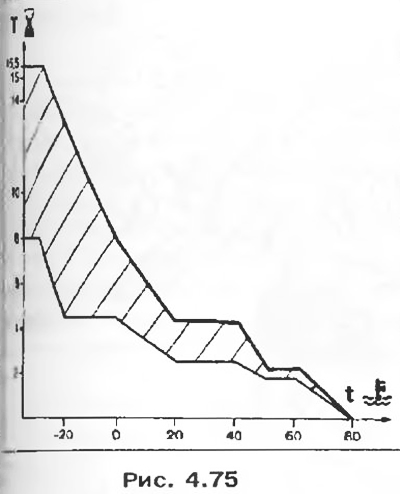
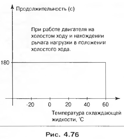
3.2. Variable post-heating mode
The variable post-heating mode starts after the end of the permanent post-heating mode. The duration of continuous activation of all 4 glow plugs depends on:
- coolant temperature;
- crankshaft speed on the engine;
- loads (injection pump lever potentiometer).
The variable post-heating mode can be interrupted:
- finally, when the coolant temperature exceeds 60°C;
- for a certain time, when the computer receives information about the presence of a full load for more than 3 seconds. The mode is restored when returning to idle or to a slight load;
- for a certain time, if the battery voltage is more than 16 V; the mode is restored when the battery voltage drops below 15V.
In all cases, the total duration of operation of the system in post-heating mode should not exceed 3 minutes.