
General description
To comply with Euro 96 standards, ESPACE Turbo Diesel is equipped with a T.P.R - EGR system (pre- and post-heating time delay and exhaust gas recirculation control).
High pressure fuel pump (injection pump) remained largely mechanical. The electronic unit controls:
- exhaust gas recirculation system (EGR);
- KSB actuators on fuel injection pump (advance of injection timing on a cold engine) and ALFB (adjustment of injection timing advance at low loads and at idle);
- glow plugs;
- fast idle control system.
Removal
- Raise the car on a lift like this. so that the wheels hang freely in the air.
- Disconnect the cable from the negative terminal of the battery.
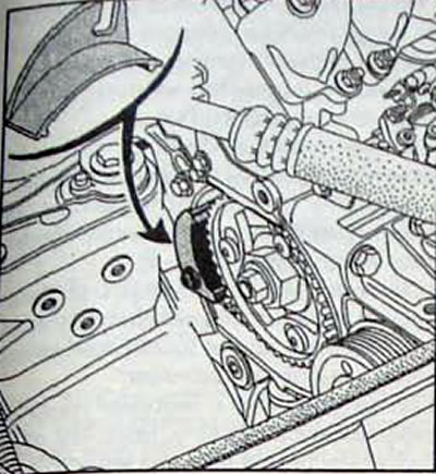
- Set the piston of the first cylinder to TDC. in this case, through the window of the timing belt casing, the mark on the camshaft pulley will be visible (pic. 3.3).
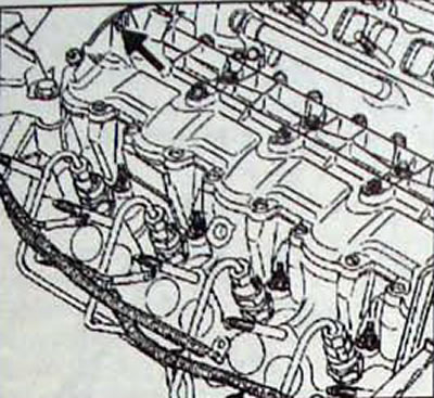
Pic. 3.3. Location of the window through which the TDC mark is visible
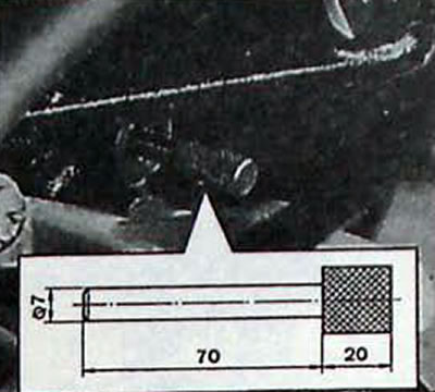
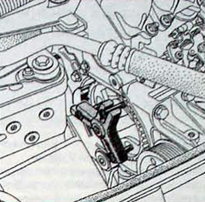
Pic. 3.4. Installation location and dimensions using tool Mot. 1318 for crankshaft locking
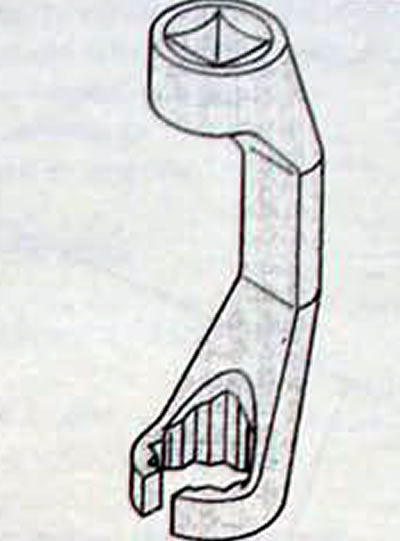
Pic. 3.5 Special wrench Mot 1383 for removing high pressure pipes
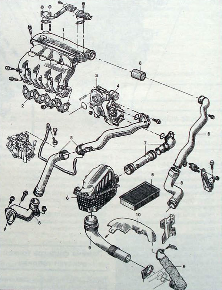
Pic. 3.6. Air supply system components: 1 - intake manifold; 2 - intake manifold gasket; 3 - turbocharger; 4 - air pressure control valve; 5 - air filter; 6 - air filter housing; 7 - air pipe for the supply of atmospheric air; 8 - air pipe for supplying forced air; 9 - air intake coupling; 10 - air intake socket
Pic. 3.7. Installing tool Mot 1317 on the high pressure fuel pump pulley
- Remove the right front wheel, plastic mud guard for engine protection and right front wheel.
- With the Mot. 1318 or a steel rod with a diameter of 7 mm, block the crankshaft. by inserting the tool into the hole closed with a plug and located on the cylinder block between the flywheel and the oil filter.
- Remove the bolt securing the power steering hydraulic system reservoir and remove the reservoir.
- Disconnect the accelerator cable and the high-idle vacuum tube from the high-pressure pump.
- Disconnect the fuel supply and return lines from the high pressure pump.
- Disconnect the electrical connectors from the high pressure fuel pump.
- Remove the plastic wiring harness protection shield on the intake manifold.
- Special key Mot. 1383 disconnect and remove the high pressure pipes.
- Remove the two bolts securing the high-pressure fuel pump rear bracket to the engine cylinder block.
- Remove the air conditioning system hose holder from the right engine pendulum mount.
- Unscrew the 2 nuts and remove the fuel filter - booster pump assembly.
- Unscrew the 3 bolts and remove the filter bracket.
- On vehicles with air conditioning, remove the plastic protective cover.
- Remove the high pressure pump pulley cover.
Note. Using the Renault Mot. 1317 allows you to remove the high pressure fuel pump without removing the pulley and timing belt.
- Install tool Mot. 1317, fixing the fuel pump pulley.
- Unscrew the nut (1, fig. 3.8) bushing fastenings on the pump, three bolts 2 bushing fastenings on the pump and three bolts (3) securing the fuel pump pulley to the bushing.
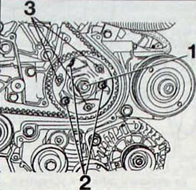
Pic. 3.8. Fuel pump pulley mounting: 1 - nut; 2 - bolt securing the bushing to the pump; 3 - bolt securing the fuel pump pulley to the bushing
- Install the T.Ar device. 1094 with three M8x125 bolts and remove the pump bushing from the conical seating surface of the fuel pump shaft.
- Remove the high pressure fuel pump.
- Remove the two bolts and bracket from the rear of the high pressure fuel pump.
Installation
Before installing the fuel pump, rotate the shaft so that the key on the shaft fits into the groove in the pulley. The key should face the high pressure outlet of the fuel pump. Use grease to glue the key to the shaft and be careful not to let it fall when installing the pump.
- Install the pump and tighten the three bolts to the required torque (2, fig. 3.8) securing the bushing to the pump.
- Screw the nut (1, fig. 3.8) bushing and tighten it to the required torque.
- Install the T.Ag device. 1094 and tighten the three bolts to the required torque (3) securing the fuel pump pulley to the bushing.
Pic. 3.9. Installation of device T.Ar. 1094 with three M8x125 bolts
- Remove the crankshaft locking device and close the hole that opens in the cylinder block with a plug.
- Remove the high pressure pump pulley support tool Mot 1317.
- Check the injection timing of the high pressure fuel pump.
- Torque the three bolts (3) securing the fuel pump pulley to the bushing.
- Rotate the engine crankshaft two full turns and check the injection timing of the fuel pump.
- Install the fuel pump rear bracket and tighten the bolts to the specified torque.
- Special key Mot. 1383 screw the high pressure lines to the fuel injectors.
- Using a special key MoL 1383, screw the fuel supply and return lines to the fuel pump.
- Connect the electrical connectors to the fuel pump.
- Connect the accelerator cable and the fast idle vacuum tube to the fuel pump.
- Install the high pressure fuel pump pulley housing.
- On vehicles with an air conditioning system, install the top! accessory drive belt casing
- Install the fuel filter bracket.
- Install the fuel filter and the booster pump, while replacing the copper seals of the pipeline connections
- On vehicles with an air conditioning system, install the air conditioning compressor pipe bracket onto the fuel filter bracket.
- Install the engine control module and check that the wiring harness is correctly positioned.
- Install the plastic wire protection shield on the intake manifold.
- Install the power steering hydraulic reservoir and secure it with the bolt.
- Remove air from the fuel system
- Connect the wire to the negative terminal of the battery.
- Install the plastic mudguard to protect the engine and the right front wheel and the right front wheel.
- Lower the car.