



Removal and installation the high pressure fuel pump
Removal the high pressure fuel pump
1. Place the vehicle on a two-post lift.
2. Disconnect the negative battery terminal.
3. Remove the right front wheel from the vehicle.
4. Remove the front section of the right front mudguard.
5. Loosen the mounting bolts and remove the engine protective pan.
6. Remove the accessory drive belt (see chapter "Mechanical part of 1.5 l diesel engine").
7. Remove the crankshaft pulley (see chapter "Mechanical part of 1.5 l diesel engine").
8. Remove the lower engine thrust rod (see chapter "Mechanical part of 1.5 l diesel engine").
9. Remove the right engine mounting support (see chapter "Mechanical part of 1.5 l diesel engine").
10. Remove the camshaft position sensor.
11. Remove the turbocharger air outlet duct.
12. Remove the high-pressure fuel line between the high-pressure fuel pump and the fuel rail (see below).
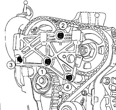
13. Unhook the fasteners (1) of the upper timing cover.
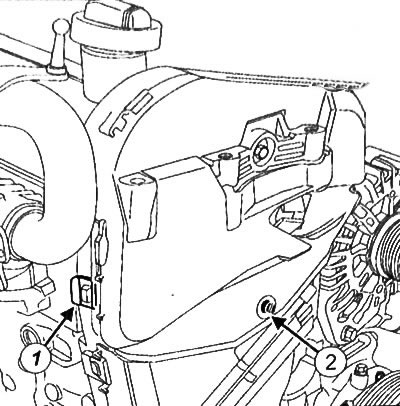
14. Loosen the bolt (2) and remove the upper cover of the timing drive.
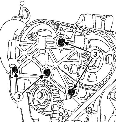
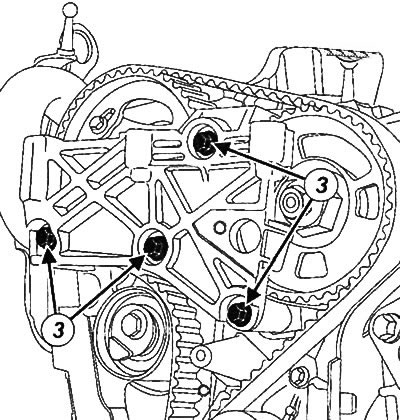
15. Loosen the bolts (3) and remove the right engine mounting bracket.
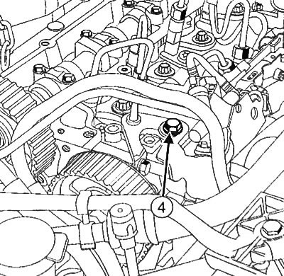
16. Loosen the bolt (4) and remove the high pressure fuel pump protection.
17. Clean the fuel supply line connector on the high pressure fuel pump.
Caution: To avoid corrosion or damage, care must be taken to protect surfaces that may come into contact with leaking fuel.
18. Disconnect the fuel supply line connector from the high-pressure fuel pump (5).
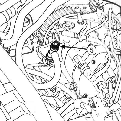
19. Install suitable plugs on the high pressure fuel pump port openings and the fuel supply line.
20. Clean the fuel return line connector on the high pressure fuel pump.
21. Disconnect the fuel injector return line from the high-pressure fuel pump (6).
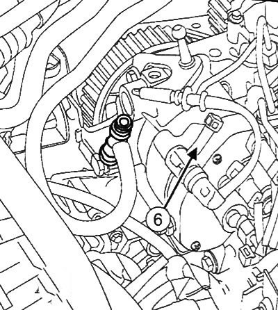
22. Install suitable plugs on the high pressure fuel pump port openings and the fuel return line.
23. Place the piston of the first engine cylinder in the top dead center (TDC) position. The hole in the camshaft pulley (7) should be opposite the hole in the cylinder head (8).
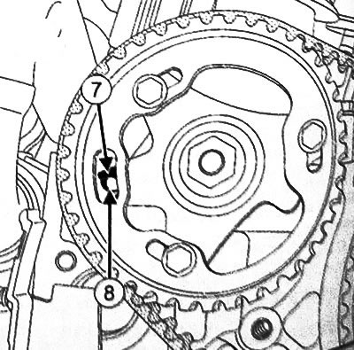
24. Insert the dowel pin from the kit (Mot. 1430) (9) into the holes in the pulley hub, camshaft and cylinder head.
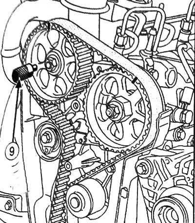
25. Remove the dowel pin from the kit (Mot. 1430).
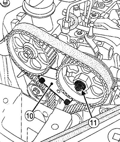
2b. Install the high pressure fuel pump retaining device (10) on the cylinder head.
Note: If necessary, slowly turn the engine crankshaft until the locking device aligns with the teeth of the high pressure fuel pump pulley.
27. Loosen the nut (11) of the high-pressure fuel pump pulley, securing the pulley from turning with a 32 mm wrench.
Note:
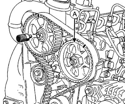
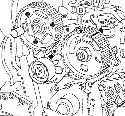
- There are two types of fuel injection pump sprockets. The first type of sprocket (A) has 6 spokes evenly spaced around the circumference of the sprocket. The second type (B) has 4 spokes unevenly spaced.
- To remove the pulley (A) of the high pressure fuel pump, use the gear puller for the conical hub of the high pressure fuel pump (Mot. 1525).
- To remove the pulley (B) of the high-pressure fuel pump, in addition to the puller (Mot. 1525), additional grips for removing the pulley of the high-pressure fuel pump (Mot. 1768) are used.
28. Install the puller (Mot. 1525) (12) on the toothed pulley of the high-pressure fuel pump.
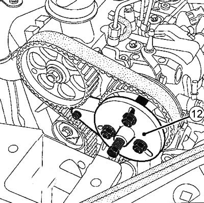
Note: Remove the spacer from the end of the toothed pulley puller pusher (Mot. 1525) to improve positioning on the high pressure fuel pump shaft.
Note: Place additional grips (Mot. 1768) on the spokes of the high pressure fuel pump sprocket to avoid damage to the pulley spokes.
29. Screw in the puller rod (Mot. 1525) until it contacts the shaft of the high-pressure fuel pump.
Note: Make sure that the puller rod (Mot. 1525) is correctly oriented and rests against the shaft of the high-pressure fuel pump. If necessary, adjust the position of the puller (Mot. 1525).
30. Loosen the bolts (13) of the high-pressure fuel pump.
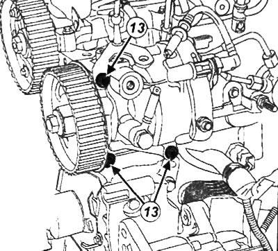
31. Gradually screw in the puller rod (Mot. 1525) to remove the high-pressure fuel pump from its place.
Note: When screwing in the puller rod (Mot. 1525), guide and support the high pressure fuel pump with one hand.
32.Remove the high pressure fuel pump.
Note: If the high pressure fuel pump is to be reused, place it in a sealed bag after removal. Remove the puller (Mot. 1525) from the high pressure fuel pump.
Installing a high pressure fuel pump
1. Check the presence of the key in the high pressure fuel pump shaft.
2. Install the high pressure fuel pump onto the cylinder head by inserting it into the toothed pulley.
Note: Make sure that the high pressure fuel pump shaft is correctly positioned relative to the toothed pulley.
3. Fit the high pressure fuel pump without tightening it.
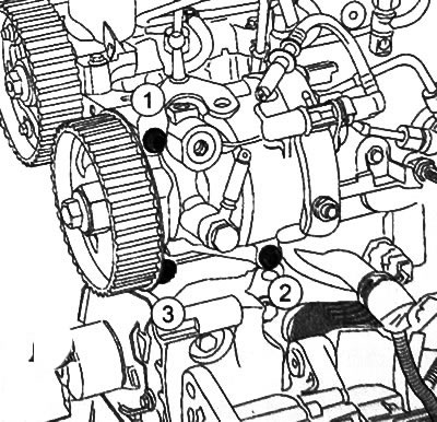
4. Tighten the high-pressure fuel pump mounting bolts in the sequence shown in the figure to a torque of 23 N·m.
5. Tighten the high pressure fuel pump pulley nut to 70 Nm, holding the pulley from turning with a 32 mm wrench.
Note: Make sure the timing belt is in good condition and installed correctly.
6. Remove the high pressure fuel pump retaining device from the cylinder head.
7. Install the right engine mounting bracket and tighten the mounting bolts in the sequence shown in the figure to a torque of 25 N·m.
8. Install the upper timing cover.
9. Tighten the upper timing cover bolt.
10. Engage the fasteners of the upper timing cover.
11. Remove the plugs from the fuel injector return line and the corresponding port on the high pressure fuel pump.
12. Connect the injector return fuel line to the high-pressure fuel pump.
13. Remove the plugs from the fuel supply line and the corresponding port of the high pressure fuel pump.
14. Connect the fuel supply line to the high-pressure fuel pump.
15. Install the high pressure fuel pump protection.
16. Install the high pressure fuel line between the fuel pump and the fuel rail.
17. Install the turbocharger air outlet duct.
18. Install the camshaft position sensor.
19. Install the right engine mounting support.
20. Install the lower engine thrust rod.
21. Install the crankshaft pulley.
22. Install the accessory drive belt.
23. Install the engine protective pan.
24. Install the front section of the right front mudguard.
Source link is located on: RenaultBook
25. Install the right front wheel on the vehicle.
26. Connect the battery.
27. Fill the system with fuel using a hand priming pump (with automatic air removal).
28. Make sure there are no fuel leaks.
29. Using the diagnostic tool, perform post-repair procedures for the injection control unit and high-pressure fuel pump.