



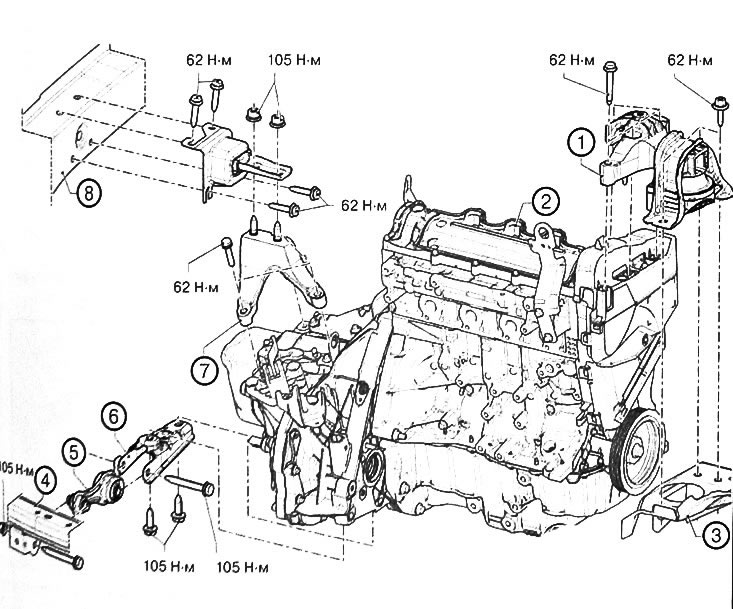
1. Cylinder head mounting support. 2. Engine with gearbox assembly. 3. Front side member. 4. Front subframe of the car. 5. Rear engine mounting support. 6. Engine thrust rod. 7. Gear plug support. 8. Front side member.
Attention:
- Use protective gloves during work.
- To avoid refrigerant leaks from the air conditioning system, be careful not to damage the pipes (do not deform, twist, etc.). To prevent atmospheric moisture from entering the air conditioning system, it is necessary to seal all openings in the refrigerant circuit in a timely manner.
Removal the power unit
Caution: To prevent the vehicle from falling off the lift, tie it to the lift with safety straps.
1. Place the vehicle on a two-post lift.
2. Remove the battery.
3. Remove the front wheels from the vehicle.
4. Loosen the mounting bolts and remove the engine protective pan.
5. Remove the front bumper from the car.
6. Remove the front mudguards.
7. Drain the engine oil from the engine.
8. Drain the transmission oil from the gearbox.
9. Drain the liquid from the cooling system
10. Disconnect the connector (1) from the diesel fuel filter.
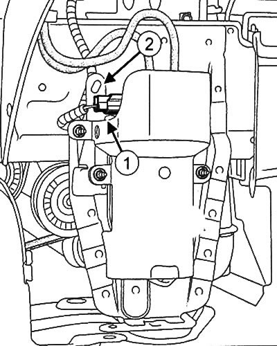
11. Disconnect the wiring from the bracket (2).
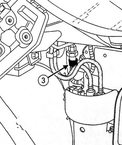
12. Disconnect the connector (3) of the air conditioning system pressure sensor.
13. Remove the air intake and air filter unit.
14. Loosen the ground busbar mounting nut (4).
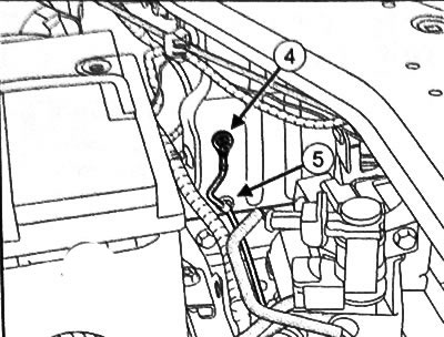
15. Unhook the wire from the holder (5).
16. Disconnect the connectors (6) from the injection control unit.
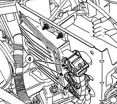
17. Remove the relay and fuse box cover.
18. Remove the side protection (7) of the relay and fuse box.
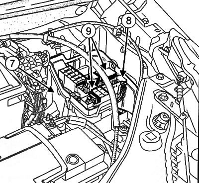
19. Disconnect the relay and fuse board (9) from the support in the relay and fuse box in the engine compartment.
20. Unscrew the bolt (10) of the ground bus from the vehicle body.
21. Disconnect the pump connectors (11).
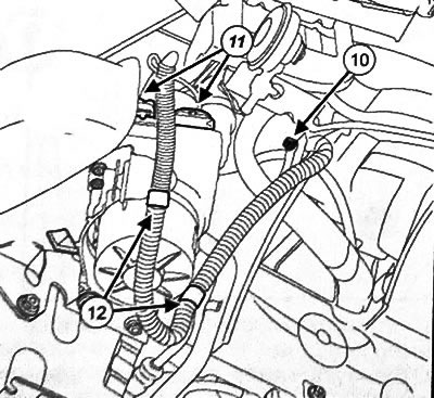
22. Disconnect the pump wiring from the holders (12).
23. Place the wiring, fuses and relays on the engine.
24. Disconnect the high pressure fuel pump return fuel line connection (13) from the fuel pump guard.
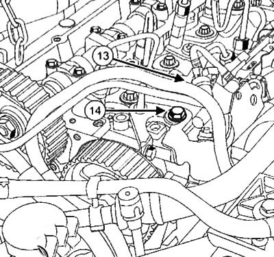
25. Loosen the bolt (14) protecting the high-pressure fuel pump.
26. Remove the high pressure fuel pump protection.
27. Disconnect the fuel supply line from the right engine mounting support cover.
28. Disconnect the fuel supply line from the high-pressure fuel pump (15).
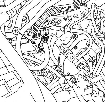
29. Install suitable plugs to the open holes of the fuel supply line and high pressure fuel pump.
30. Disconnect the return fuel line from the right engine mounting support cover.
31. Install suitable plugs on the disconnected fuel return line and the high pressure fuel pump return port opening.
32. Disconnect the fuel lines from the holders (19).
33. Remove the low pressure hose of the power steering pump using hose clamp pliers (Mot. 1448) and drain the working fluid from the hydraulic circuit of the power steering.
34. Remove the high pressure line from the power steering pump.
35. Install plugs on the opened holes.
36. Disconnect the connector (23) of the pre-start heating system
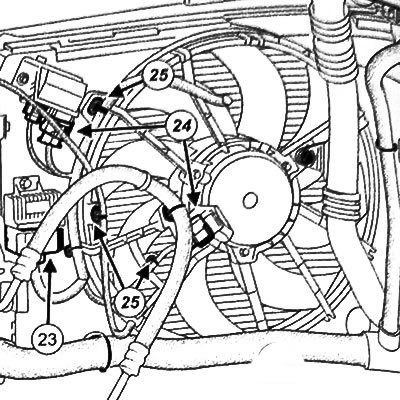
37. Disconnect the connectors (24) of the cooling system electric fan drive.
38. Disconnect the fan wiring from the holders (25).
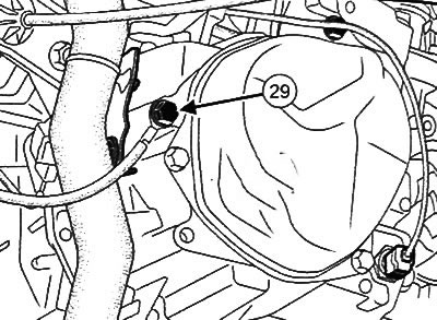
39. Unscrew the bolt (29) of the ground bus from the gearbox.
40. Remove the intercooler outlet and inlet pipes (intercooler).
41. Remove the air-to-air intercooler (intercooler).
42. Loosen the bolts (30) connecting the pipelines to the compressor.
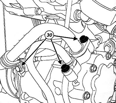
43. Disconnect the compressor pipes and immediately seal the holes with plugs.
Note: Plug the hoses to prevent atmospheric moisture from entering the air conditioning system.
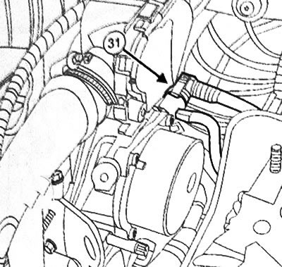
44. Disconnect the vacuum line (31) from the vacuum pump.
45. Disconnect the cooling system hose clamps (32) from the heater radiator using hose clamp pliers (Mot. 1448).
46. Disconnect the cooling system hoses from the heater radiator.
47. Remove the cooling system hoses from the holders.
48. Disconnect the upper hose from the cooling system chamber.
49. Disconnect the water pump inlet hose.
50. Loosen the mounting bolts and remove the heat shield on the steering gear.
51. Loosen the bolts securing the steering gear to the subframe and tie the steering gear to the car body.
52. Remove the right and left front drive shafts.
53. Using a screwdriver, disconnect the gear shift control cables from the gearbox (35).
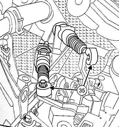
54. Squeeze the clamps (A) to detach the gear shift control cables from the thrust bushing holders.
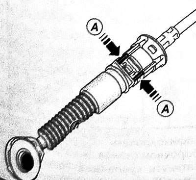
55. Remove the gear shift control cables from the gearbox.
56. Disconnect the clutch drive lines from the clutch master cylinder.
57. Collect the leaking brake fluid in a suitable container.
58. Seal open holes in pipelines with plugs.
59. Remove the engine thrust:
- Loosen the bolt securing the engine's reaction rod to the subframe.
- Loosen the bolt securing the engine's thrust rod to the support.
- Remove the engine thrust rod.
- Loosen the engine thrust support mounting bolts and remove it.
60. Remove the front subframe from the vehicle.
61. Loosen the exhaust flange nuts.
62. Move the exhaust pipe to the side.
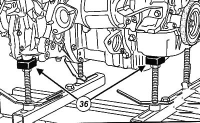
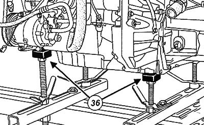
63. Place the engine/gearbox assembly removal/installation stand (Mot. 1390) under the engine with gearbox.
Note: Ensure that the engine/gearbox assembly removal/installation stand supports (Mot. 1390) are correctly positioned under the power unit.
64. Remove the right engine mounting support:
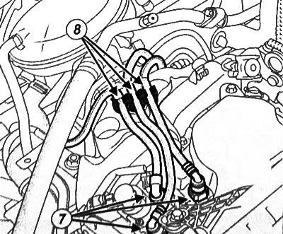
- Disconnect the fuel line connectors (7) and unhook the fuel lines (8).
- Move the expansion tank of the cooling system to the side.
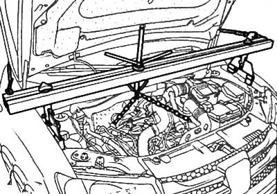
- Install the engine support beam with multiple adjustments and rigging (Mot. 1453) by attaching the engine rigging eye to the timing drive side.
Note:
- Some vehicles are not equipped with engine rigging eyes on the timing side.
- Rigging eyes can be purchased separately by placing an appropriate order from the spare parts catalog.
- Always use new bolts to secure rigging eyes.
- Mark the position of the right engine mounting support on the body.
- Loosen the bolts securing the right mounting support to the engine.
- Loosen the bolts securing the right engine mounting support to the body.
- Remove the right engine mounting support.
65. Loosen the nut on the left engine mounting support:
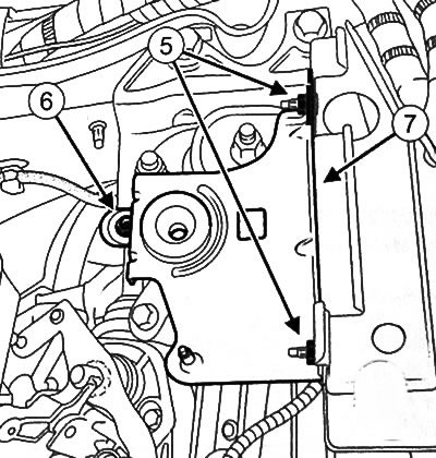
- Unscrew the nuts (5) and bolt (6) and remove the air filter shelf (7).
- Mark the position of the left engine mounting support on the body.
- Loosen the nuts and bolts securing the mounting support to the gearbox.
- Loosen the bolts securing the left mounting support to the body and remove the left mounting support.
66. Use a copper hammer to drive in the gearbox stud to separate the engine and gearbox assembly from the car body.
67. Raise the car with a lift to remove the engine and gearbox from the car.
Note: Make sure that the engine and gearbox do not interfere with the body.
68. Remove the support stand with the power unit (engine and gearbox assembly) from under the car.