
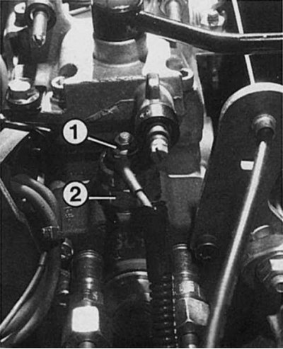
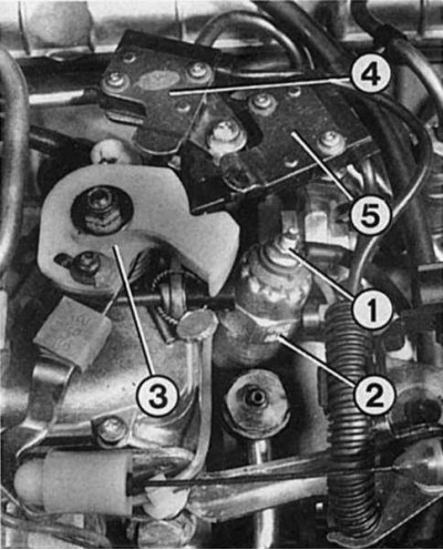
- 3 - cam disc «throttle control rods» to switch on the microswitches for exhaust gas recirculation and full load;
- 4 - microswitch for exhaust gas recirculation;
- 5 - full load switch.
 |  |
Vane fuel priming pump
The main element in the distribution injection pump is a vane fuel priming pump. It sucks fuel from the pipeline coming from the filter. The pump wheel, into which movable sliders are inserted, is located in a round hole in the casing. When the pump sprocket is turned, a certain volume always remains between the sliders, which then decreases towards the pump discharge, that is, towards the outlet. The liquid contained in this volume is thus forcibly squeezed out.
The vane fuel priming pump supplies fuel under pressure to the high pressure fuel pump housing. It is located on the same shaft as the vane fuel priming pump - the injection pump distribution plunger, from whose name the high-pressure distribution fuel pump got its name.
Injection pump distributor plunger and cam disc
The secret of the fuel injection pump distribution plunger is that it has many holes and recesses. Thus, it can perform its two main functions - filling and spraying.
Principle of operation: during filling, the slotted slot of the distribution plunger is located opposite the filling hole. Fuel from the vane pump under pressure enters the free space in the piston and in front of the piston. The injection pump distributor plunger rotates further. The filling hole closes again. Filling completed.
Now 2 other structural elements come into play. The distribution plunger of the high-pressure fuel pump is connected to a pulley on which 4 protrusions are located. This is a cam disc; it runs against a counter-support that carries 4 rolls at the same interval as the lugs on the cam disc to reduce friction. This is a roller ring. Splashing then takes place: the cam disc moves on a roller ring. If its protrusions have reached the break-in, then the cam disc presses the distribution plunger of the high-pressure fuel pump forward. This happens when the next hole in the control plunger aligns with the outlet port to the injector. Fuel can only flow out in the direction of the cylinder in which compression and ignition take place. Due to the movement of the distribution plunger of the injection pump forward, the amount of free space in front of it is reduced. The fuel already under pressure enters the injector. The injection process in the cylinder is completed. Crankshaft and high pressure fuel pump (injection pump) rotate further. The injection pump control plunger slides back and fuel flows out of the filler hole.
The injection pump control plunger pivots to the outlet port for the next cylinder. The protrusions of the cam disk again engage with the rollers of the overrunning ring. The injection pump control plunger is pushed forward and fuel is injected under pressure.
Solenoid Control Disable Device
Before diesel fuel enters the fill port of the injection pump distributor plunger, it passes through an electric solenoid operated valve - a solenoid control shut-off device. It turns on when the ignition key is turned to the first position and clears the way for fuel. When the engine is turned off, the electricity supply is interrupted by the start switch. The solenoid control shut-off device then closes the fuel supply channel and the engine stops. There is no other way to turn off the diesel other than shutting off or plugging the air filter or exhaust snorkel.
Centrifugal regulator
In order to register the various operating conditions of the engine and thus allow the required amount of fuel to be injected, a centrifugal governor is installed in the high pressure fuel pump, which is also sometimes called an all-speed governor. Its weights are pressed outward depending on the engine speed. Weights act through the lever mechanism on the control sleeve, which opens a hole in the injection pump distributor plunger to remove excess fuel. If the engine speed increases sharply in relation to the position of the gas pedal, then the regulator opens the said hole, and the speed decreases again. When the engine is started, this hole is completely closed. The engine receives the maximum amount of fuel, but only until the set idle speed is reached. Then the regulator starts working again.
The same thing happens at idle and at partial load. The centrifugal governor equalizes the position of the throttle control pedal and the engine speed through the mechanics described above. If the ratio between the position of the gas pedal and the speed is reached, then the removal of excess fuel begins. The maximum number of engine revolutions is also limited by the centrifugal governor. If the engine speed exceeds the maximum allowable limit, then the centrifugal governor opens a hole to drain excess fuel. Thanks to this, the engine runs without exceeding the maximum allowable limit.
Fuel Injection Advance Electromagnetic Clutch
As the engine speed increases, the fuel must be injected earlier in order to ignite in time. This ignition timing advance is carried out by the fuel injection advance clutch. It is also installed in the high pressure fuel pump.
If the engine speed increases, then the vane priming pump also rotates with increasing speed in the high pressure fuel pump. Due to this, the fuel pressure increases, and this is used by the fuel injection advance clutch. Fuel pressure acts on the plunger and moves it, compressing the spring. The roller ring is rigidly connected to this plunger. With an increase in fuel pressure - at a higher speed - the plunger rotates the roller ring around its axis. The cams of the cam disc therefore act on the rollers earlier; thus injection occurs earlier. When the speed decreases, the plunger lags a little and, accordingly, the roller ring with it.
Cold start device
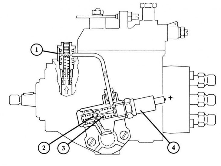
The cold start hydraulic accelerator on the Bosch high pressure fuel pump consists of a restrictor valve (1), reducing valve (3) and electrically heated thermoelement with expanding material (4). If the cold engine speed exceeds 2000 rpm, then the ball valve opens (2) and normalizes the increased fuel pressure.
A cold engine starts better if fuel is injected into hot compressed air earlier. In this case, the car accelerates better in the first phase of the operation of a cold engine, and thanks to this device, annoying blue exhaust smoke is almost completely absent at start-up. Said cold start accelerator operates in the high pressure fuel pump as a fuel injection advance clutch. It acts by means of fuel pressure on the plunger of the fuel injection advance clutch and presses it back. The roller ring is therefore rotated by approx. 2.5°in the direction «advancing». The cold start device consists of a side-mounted valve in the injection pump, which is directly connected to an electrically heated thermocouple screwed into the valve body. After starting the engine, the thermocouple increases in size and opens the valve. As a result, the injection pressure is reduced to an average rate, and the cold start accelerator no longer works after that. This happens depending on the ambient temperature after 30-180 seconds.
If the coolant temperature is over 65°C and therefore the fuel temperature is over 45°C or 67°C (depending on the type of high pressure fuel pump, the cold start accelerator remains off. If the speed increases more than 2000 rpm, then the valve opens without the participation of the cold start accelerator.
Regulator «quick» idle move
For comfort, the high pressure fuel pump, in addition to the cold start accelerator, has a device for increasing the speed. Thus, it is possible to avoid annoying beating and vibration at idle with a cold engine.
To do this, the idle speed limiter is equipped with a second lever, which is connected via a small Bowden cable to a wax thermostat screwed into the engine housing, heated by the coolant. On a cold engine (coolant temperature below 15°C) using this lever, the idle speed is increased to 1100-1200 rpm. As the engine heats up, the wax in the thermostat melts and expands. The cable tension loosens and the idle lever approaches the normal idle speed limiter.