



Contents: Disassembling the injector 🠛 Solenoid Control Shut-Off Device…🠛 Driving with a faulty solenoid…🠛 Malfunctions: Thermal switch of the…🠛 The cold start accelerator is faulty 🠛 Removal the cold start accelerator…🠛
Injector elements
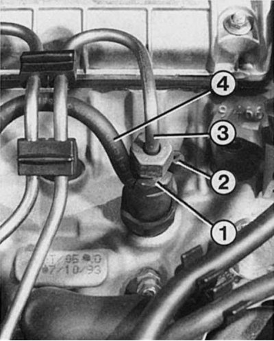
1 - nozzle; 2 - plugs on the free fuel outlet pipe of the 4th cylinder injector; 3 - high pressure injection line; 4 - connecting hose between two nozzles.
Roto High Pressure Fuel Pump Components
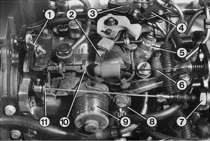
1 - idle speed adjusting washer; 2 - throttle lever; 3 - exhaust gas microswitch; 4 - full load micro switch; 5 - solenoid control shutdown device; 6 - throttle control cable; 7 - device for moving the "fast" idle speed membrane; 8 - boost pressure regulator; 9 - electromagnetic clutch for fuel injection advance; 10 - idle speed stabilization limiter; 11 - "fast" idle speed lever.
Four tension bolts are responsible for controlling the speed of the Bosh high-pressure fuel pump.
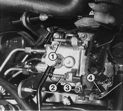
1 - full load limiter; this limit screw is protected by a factory seal (adjustment of this bolt is carried out only on a special test bench);
2 - persistent (restrictive) idle speed stabilization screw;
3 - limit screw for adjusting normal idle speed;
4 - limit screw for adjusting the "fast" idle speed.
Source is located on the website Renaultbook.ru
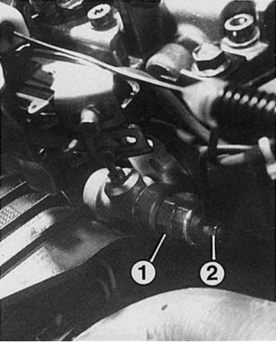
Since the thermal switch (1) of the cold start accelerator affects the fuel injection advance clutch, its failure creates difficulties not only during engine start-up, but also during the warm-up period. The number "2" indicates the electrical connector that must be disconnected when checking the switch.
Below are some of the jobs that make sense to do yourself. For example, sealing a leaking high-pressure fuel pump. This defect often appears in the position change lever (the "combustible mixture" lever). To fix this kind of malfunction, it is better to contact a car repair shop.
1. Purchase a new heat shield for each injector.
2. Disconnect the battery terminals and cover the generator with a rubber mat to protect it from diesel fuel.
3. Remove the injection pipes and stick adhesive tape to prevent dirt from entering.
4. Remove the drain pipes and apply adhesive tape to the fuel pump and injector holes to prevent dirt from entering. Wipe off any remaining diesel fuel with a clean cloth.
5. Unscrew the injectors with a SW 27 wrench; be careful not to drop the injectors.
6. If the heat shield is located in the nozzle opening, remove it using a plastic ballpoint pen or wire hook.
7. Use only a new heat shield for installation.
8. Tighten the injectors to a torque of 70-80 Nm and the union nuts of the high-pressure fuel lines to a torque of 15-25 Nm.
Note: Recommendation: depending on the type of high pressure fuel pump (especially export cars!) and because of this different fuel pressure, each pump is equipped with specially adjusted nozzles. Therefore, when buying spare parts, you should always buy only the right parts.
Disassembling the injector
If the injector is dirty, it is necessary to disassemble it. It is better to completely replace the faulty injectors with new ones. When disassembling, it is important to remember: the injector cannot be left open, it must be installed immediately and then let the engine run. Otherwise, the injector parts can quickly rust to each other. Tightening torque of the lower and upper parts of the injector: 70 Nm.
Note: Recommendation: When checking the injector, always make sure that the jet from the injector is directed away from you. The injection pressure is so strong that it can cause damage if it comes into contact with the skin.
Solenoid Control Shut-Off Device Malfunctions
1. The solenoid control shut-off device for stopping the engine shuts off the fuel supply to the injectors. The solenoid control shut-off device is suspect if the engine does not start despite the preheating device being in good condition and the tank being full. The sequence for checking the solenoid control shut-off device is:
2. While the assistant turns the ignition key, listen to see if the solenoid control cutoff makes a clicking sound. If there is no clicking sound, there is no power or the solenoid control cutoff itself is faulty.
3. Power supply test: Turn on the ignition and connect the test lamp to the contacts of the solenoid control cut-off device.
4. If it lights up, the solenoid control shutdown device is faulty.
5. If it does not light, then the wire coming from the ignition switch is faulty. There is no fuse in the connection.
Note: Recommendation: With the ignition on, the solenoid control cut-off device should become hot after a while.
Driving with a faulty solenoid control cut-off device
If the solenoid control shut-off device is faulty or is not receiving power, you can still continue driving. To do this:
1. Clean work surfaces around the solenoid control shut-off device.
2. Disconnect the wire from the solenoid control disconnect device.
3. Unscrew the solenoid control shut-off device from the high pressure fuel pump.
4. Remove the valve piston and spring from the solenoid control shut-off device.
5. Screw the housing back into place to act as a seal.
6. The engine will start as usual, but to stop it you will need to turn off the engine by engaging the gear.
Note: Leak in the throttle lever connection (gas lever) high pressure fuel pump can be eliminated by replacing the throttle lever shaft sealing ring. This work is carried out in a Renault or Bosch workshop.
Malfunctions: Thermal switch of the cold engine start accelerator
A faulty thermal switch can only be detected at low temperatures. To do this, start the engine on a cold engine, with the thermal switch wire removed, and then connect the wire to the thermal switch. If the speed changes noticeably, the thermal switch is OK. Checking the power supply:
1. Check if there is electric current. To do this, connect a test lamp to the contacts of the thermal switch and turn on the ignition.
2. If the indicator lamp does not light, then the ignition switch wire is faulty; however, this means that the solenoid control shut-off device also does not work.
The cold start accelerator is faulty
A faulty cold start accelerator can only be accurately determined on a cold engine (coolant temperature below 15°C).
1. Start the engine and observe the movement of the high pressure fuel pump fast idle lever, whether it moves slowly to the other limiter.
2. Turn off the ignition - after a while the thermal switch should pull the cold start accelerator lever again.
3. Check with a cold engine running: the speed should decrease noticeably after 1/2-3 minutes.
Removal the cold start accelerator actuator
1. Remove the connecting rod from the idle lever. To do this, unscrew the screw nipple and remove it from the rod.
2. Unscrew the thermal switch with Bowden cable from the cylinder head.
3. After setting the thermal switch on a cold engine, press the idle speed lever to the stop for "fast" idle, insert the screw nipple and tighten so that the "fast" idle speed lever is in the "fast" idle position. Check the speed (1110-1200 rpm).
4. When the operating temperature is reached (the fan should turn on once) the gap on the tensioned cable from the screw nipple to the idle lever should be 2-3 mm.