
Note. Be careful not to allow dirt to enter the pump or nozzle tubes. When installing, use new O-rings on "banjo" fuel line connections.
Removing
F8Q engines
1. On F8Q 620 engines with air conditioning, proceed as follows.
2. To gain access to the fuel pump mounting bolts, it is necessary to remove the alternator and its bracket.
3. Disconnect the ground cable from the battery (contact the head Engine electrical equipment for Scenic models).
Attention! If the car radio in your car is coded, make sure you know the code before disconnecting the battery.
4. Remove the generator as described in Chapter Engine electrical equipment, then proceed as follows.
5. Remove the mounting bolts and remove the power steering pump pulley from the pump drive flange. Please note that when loosening the bolts, it is necessary to hold the pulley (e.g. using an old drive belt).
6. Turn away bolts of fastening and remove an arm with an auxiliary directing roller of a driving belt.
7. Remove the top two bolts securing the air conditioner compressor to the alternator bracket.
8. Engage the handbrake, jack up the front of the vehicle and place it on axle stands. Where available, remove the lower engine cover.
9. Remove the right forward wheel and an insert of an arch of a wheel.
10. Loosen the bottom A/C compressor mounting nuts and bolts, then rotate the compressor down so that the alternator bracket can be removed from the top.
11. For all models, proceed as described in the following paragraphs.
12. If not done yet, disconnect ground cable from battery (contact the head Engine electrical equipment for Scenic models).
13. Turn away and remove a cover of the right top support of the engine.
14. Rotate the crankshaft to set the #1 piston to TDC on the compression stroke and insert the dowel pin to check the position of the crankshaft as described in Chapter Engine repair.
15. Turn away bolts of fastening and remove a cover of a gear drive belt which closes a gear wheel of the fuel pump.

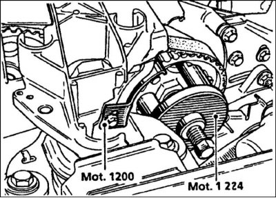
16. If there is a tool to hold the fuel pump pulley (Renault Mot. 1200), remove the dowel pin, rotate the crankshaft from TDC by one tooth of the camshaft pulley and insert the holding tool into the fuel pump pulley (refer to accompanying illustration).
17. If the specified tool is not present, remove a gear driving belt as it is described in the Head Engine repair.
18. Disconnect the gas pedal cable from the fuel pump, refer to Section Removal, installation and adjustment of the throttle cable if it is needed.
19. On F8Q 620 engines with a fast idle thermal drive, disconnect the fast idle cable from the fuel pump (refer to section Removing, installing, checking and adjusting the thermal actuator and fast idle cable). On models with a fast idle vacuum drive, disconnect the cable from the pump lever and the vacuum hose from the drive (refer to section Removal, installation, check and adjustment of components of system of fast idling).
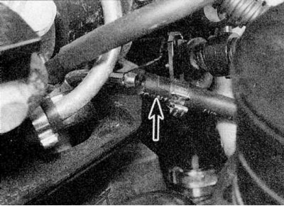
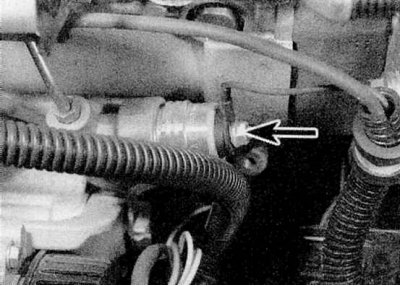
20. On models with a turbocharger, disconnect the hose connecting the boost pressure corrector to the intake manifold (refer to accompanying illustration).
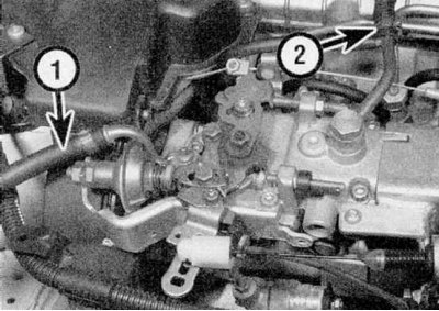
21a. Remove the banjo bolt and disconnect the fuel supply hose from the fuel pump. Cover the open end of the hose or pipe and plug the fitting on the fuel pump to keep dirt out.
21b. Do the same with the main return hose (refer to illustrations).
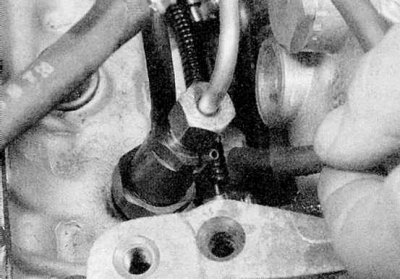
22. Disconnect the main fuel return hose from the fuel injector (refer to accompanying illustration).
23. Where applicable, disconnect auxiliary fuel return hose from pump. On models with a turbocharger, the auxiliary hose is connected to the boost pressure fuel corrector at the pump (refer to accompanying illustration).
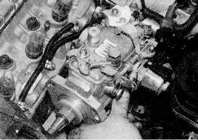
24. Disconnect all electrical wiring from the pump. Note that on some pumps this can be done by simply unplugging the wiring from the connectors on the pump. On some pumps it is necessary to disconnect the wiring from individual components (some connections can be protected by rubber sheaths) (refer to accompanying illustration). On engines with Lucas pumps, disconnect the wiring from the following units: coded solenoid valve, injection timing corrector, and throttle lever potentiometer.
25. Turn away the connecting nuts fastening tubes to the fuel pump and atomizers. Remove the tube assembly. Close open couplings to prevent dirt from entering. Please note that the fuel injectors must be removed from the fuel injectors to be able to close the injectors (refer to accompanying illustration).
26. Where applicable, remove the alternator plastic shield below the fuel pump. Note the location of the brackets attached with nuts and bolts.
27. On the F8Q 620 engine, proceed as follows:

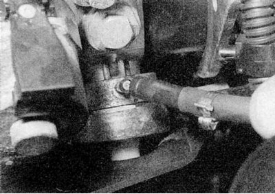
28. Turn away a fixing nut of a pulley of the fuel pump and remove a washer. If there is no tool to hold the pulley (refer to illustration), block the pulley with a homemade tool inserted into the holes in the pulley (but not in the teeth of the pulley).
29. Mark the location of the gear wheel relative to the end of the pump shaft. This must be done whether the toothed drive belt has been removed or not, as the pulley has two key slots (for use with various types of fuel pumps).
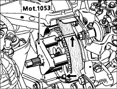
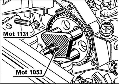
30a. Install Renault special tool (Mot. 1053) on the pump gear (refer to accompanying illustration). Before removing the pulley, we advise you to fasten the toothed drive belt using two plastic ties.
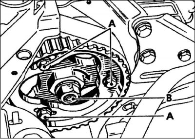
30b. Adjusting bolts A and fastening nut B. Before removing the pump, turn the base in the direction of the arrow.
30c. Removing the whole gear.
30d. Removing the compound gear
Note. The puller must be located in the pulley holes, and not on the teeth. for pulley "IAA" a special puller is required, which is installed on the pulley hub.
31. Remove the puller. If the fuel pump pulley holding tool is installed and the toothed drive belt has not yet been removed, do not remove the pulley.
32. On F8Q 784, 786 and 788 engines, proceed as follows:
Attention! On early versions of these engines (predominantly F8Q 784), pulley "IAA" fastened to the fuel pump shaft with a conventional nut with a separate washer. You will need a special Renault puller (Mot. 1357 - refer to paragraphs 33-40 below), mounted on the pulley hub. On later engines (predominantly F8Q 786 and F8Q 788), pulley "IAA" fastened to the pump shaft with a non-ferrous metal nut with a washer that acts as a puller. The pulley can be released from the pump shaft by loosening the nut - refer to paragraphs 55-58 below. Before starting work, determine how the pulley is attached.
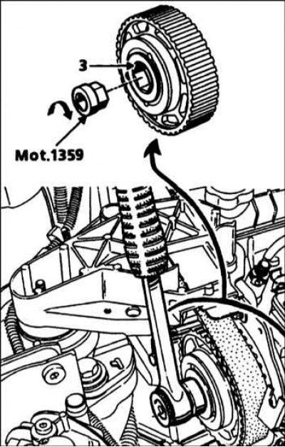
33. Using a special Renault tool (Mot. 1359), remove the center bolt of the gear with plate: the bolt has a left-hand thread (refer to accompanying illustration).
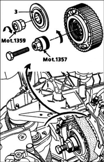
34. In place of the central bolt, screw in the Renault special tool (Mot.1357). Then screw a 40 mm M12x125 bolt into the tool to release the pulley (see illustration).
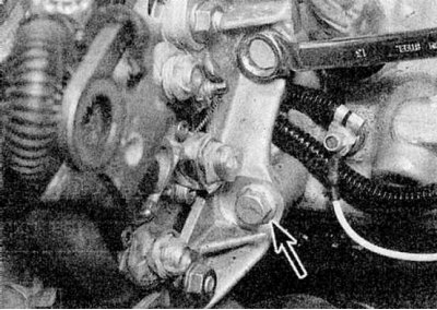
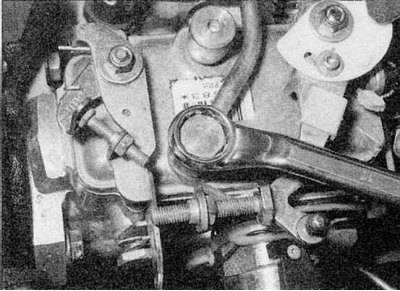
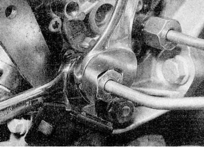
35. On all models, remove the bolts and nuts securing the fuel pump left support bracket to the cylinder head (refer to accompanying illustration).
36. Check again that all pipes, hoses and wires have been disconnected from the pump.
37. Apply marks for subsequent alignment of the pump and bracket.
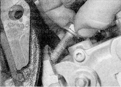
38a. Loosen the three mounting bolts.
38b. Remove the pump from the bracket, leaving the pulley with toothed belt in place (refer to illustrations). On F8Q 620 engines, the bottom mounting bolt is easiest to access on the left side of the pump. This procedure will require a special Renault tool (Mot. 902-02). If not available, use a deep socket and an extension rod. On engines with a Lucas pump and pulley type "IAA", unscrew the bolts with a T40 socket wrench, the minimum length of which must be 60 mm - and move the pump back.
39. Remove the key from the end of the pump shaft if it is loose.
40. If required, the gas pedal cable bracket can be unscrewed from the pump.
F9Q engines
1. Disconnect the ground cable from the battery (contact the head Engine electrical equipment for Scenic models).
Attention! If the car radio in your car is coded, make sure you know the code before disconnecting the battery.
2. Disconnect the electrical wiring of the electronic control module, then turn away the bolts and remove the electronic control module from the bracket.
3. Disconnect the two fuel hoses from the top of the fuel filter.
4. Disconnect the pump harness at the main connector attached to the ECM bracket. The electrical wiring is released from the mounting brackets and moved to the side.
5. Disconnect the wiring connector from the fuel heater on the filter.
6. Turn away bolts and remove assemblage of the fuel filter and an arm of the electronic control module.
7. Turn away and remove a cover of the right top fastening of the engine and a cover of a cogwheel of the fuel pump.
8. Rotate the crankshaft so that #1 piston is at TDC on the compression stroke and insert the dowel pin to check the crankshaft position as described in Chapter Engine repair.
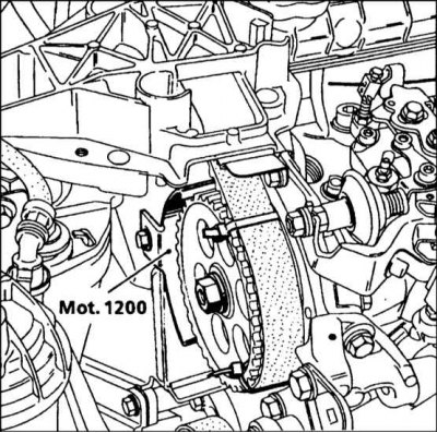
9. Install the holding tool on the fuel pump gear (Renault Mot. 1200) (see illustration).
10. Disconnect the fuel return hose connector from the pump. Cover the open ends of the hose to prevent dirt from entering.
11. Disconnect the main fuel return hose from the fuel injector.
12. Disconnect the two electrical connectors at the base of the fuel pump.
13. Remove the union nuts securing the injector tubes to the fuel pump and injectors. Remove the tube assembly. Close the couplings to prevent dirt from entering.
14. Turn away the bolts fastening an arm of the left support of the fuel pump to the block of cylinders.
15. Mark pump and right foot. This will help when installing the pump.
16. While inserting a suitable head through the slots in the pump gear, loosen the three bolts on the right pump support.
17. Mark the position of the gear wheel relative to the pump shaft to ensure correct installation, then loosen the center nut securing the pulley to the pump shaft.
18. Alternately, continue to loosen the pump bolts, then the gear wheel mounting nut, until they are completely loosened. Remove the pump from the pulley and right hand support, leaving the pulley in place, engaged with the toothed drive belt. Remove the key from the end of the pump shaft if it is loose.
The position of the Bosch injection pump gear (cylinder #1 at TDC)
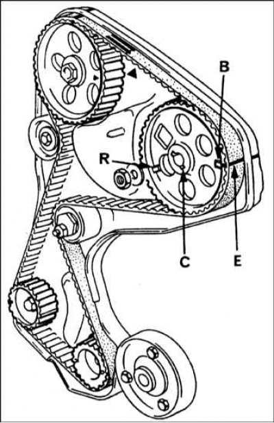
B - Alignment mark on the pulley for the Bosch fuel pump; C - Slot for a segment key; R - Alignment mark on the pulley for the Lucas fuel pump; E - Timing belt mark
Lucas injection pump gear position (cylinder #1 at TDC)
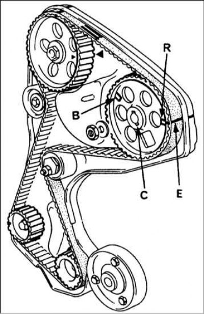
B - Alignment mark on the pulley for the Bosch fuel pump; C - Slot for a segment key; R - Alignment mark on the pulley for the Lucas fuel pump; E - Mark on the timing belt
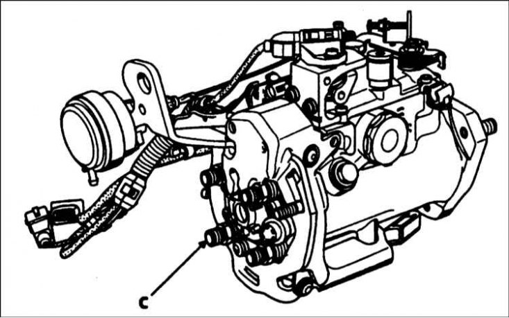
The segment key on the pulley must be aligned with the output "WITH" for nozzle No. 1 - pump Lucas
Installation
F8Q engines
1. Where applicable, attach left pump support bracket and throttle cable bracket to pump.
2. Begin installation by placing the slotted key on the end of the pump shaft. On F8Q 784, 786 and 788 engines, the key must be inserted into the slot aligned with the No. 1 injector exit axis (refer to the accompanying illustration above "Segmented key on pulley"). On all motors, make sure the pump shaft is completely dry.
3. Install the pump on the right bracket. If the pulley is in place, insert the pump shaft into the pulley. Align the marks made on the pulley and pump shaft. On the F8Q 620 engine, make sure the slotted key is inserted into the right slot in the pulley (refer to the illustrations above "Injection pump gear position"). 62 Where applicable, align the marks made on the pump and the right bracket, and if a new pump is being installed, redraw the mark from the old pump to provide an approximate fit.
4. Install and lightly tighten the right pump support bolts. On the F8Q 620 engine, access to the lower mounting nut can be improved by removing the No. 4 injector (refer to section Check, removal and installation of nozzles). Install the bolts and nuts securing the left fuel pump bracket to the cylinder head and tighten them, but do not over tighten.
5. On the F8Q 620 engine, install the washer, then tighten the pump gear mounting nut to Specifications force, blocking the pulley as during removal (refer to accompanying illustration).

6. On F8Q 784, 786 and 788 engines, install the cogwheel center bolt using the Renault Mot. 1359 (refer to illustration), and tighten it with a tightening torque of 90 Nm. Using the Renault special tool used in the removal, block the pulley and install the retaining nut, tightening it with the tool shown in Specifications effort.
7. On all engines, if the toothed drive belt has been removed, install and tighten it as described in Chapter Engine repair.
8. Where applicable, remove the retaining tool from the gear, then set the #1 piston to TDC on the compression stroke as described in Chapter Engine repair.
9. Check and adjust the moment of injection as described in Sections Methods for checking and adjusting injection timing or Checking and adjusting injection timing.
10. Install the plastic shield under the pump.
11. Install and connect the fuel injector lines and tighten the couplers.
12. Connect all electrical wiring to the pump.
13. Connect the supply and return fuel pipes and hoses, and tighten the bolt "banjo" connections given in Specifications effort. Use new sealing washers. Also connect the outlet hoses.
14. Connect the gas pedal cable and adjust it as described in Section Removal, installation and adjustment of the throttle cable.
15. On F8Q 620 engines with air conditioning, reverse the steps in the paragraphs above. Establish and tighten an auxiliary driving belt, acting according to the description in the Head Maintenance.
16. Where applicable, on models with a fast idle thermal actuator, connect and adjust the fast idle cable as described in Section Removing, installing, checking and adjusting the thermal actuator and fast idle cable, but remember that the final adjustment must be made after the engine has warmed up to normal operating temperature.
17. On models with a fast idle vacuum drive, connect the hose to the drive, and check the fast idle cable length adjustment as described in Section Removal, installation, check and adjustment of components of system of fast idling.
18. Install the timing belt cover onto the fuel pump gear and upper right engine mount cover, and tighten the bolts securely.
19. Check switch adjustment "no load" as described in chapter Engine electrical equipment.
20. Connect the mass cable to the battery.
21. Fill and prime the fuel system as described in Section Filling and bleeding the fuel system.
22. Start the engine and check up turns of idling and turns of deceleration, as it is described in the Section Checking and adjusting idle speed and deceleration speed.
F9Q engines
1. Install a slotted key on the end of the pump shaft.
2. Mount the pump on the right foot and insert the pump shaft into the gear wheel. Align the marks made on the pulley and pump shaft.
3. Where applicable, align marks made on pump and right foot. If a new pump is being installed, redraw the label from the old pump to provide an approximate fit.

4. Lightly tighten the right support bolts, then install the pulley center bolt using the Renault Mot special tool. 1359 (refer to illustration). Tighten it with a tightening torque of 90 Nm. Using the Renault special tool, block the pulley, install the fixing nut and tighten it to the Specifications effort.
5. Install and tighten the bolts securing the left pump support bracket to the cylinder head.
6. Install and connect the fuel injector lines and tighten the couplers.
7. Install the toothed drive belt cover onto the fuel pump gear and upper right engine mount cover and securely tighten the bolts.
8. Install the fuel filter assembly and ECM bracket.
9. Connect supply and return fuel pipes and hoses.
10. Install the electronic control module and connect all electrical wiring to the pump.
11. Lower the vehicle to the ground and connect the earth cable to the battery.
12. Fill and prime the fuel system as described in Section Filling and bleeding the fuel system.
13. Finally, check and adjust the injection timing (refer to section Checking and adjusting injection timing).