
English Русский
Български
Беларускі
Український
Српски
Hrvatski
Română
Polski
Slovenský
Magyar
Bookmark Contacts Articles Sitemap
Company vehicles Peugeot Company vehicles Opel Company vehicles Skoda Company vehicles Land Rover Company vehicles Mitsubishi Company vehicles Volkswagen Company vehicles Honda
RenaultBook.ru


Duster   Fluence   Kangoo   Laguna   Logan   Megane   Sandero   Scenic   Symbol   Clio   Other
Megane 1 (1995-2002) Megan 2 (2002-2009, petrol)

Removal and installation a turbocharger (Renault Megane 1)

  • Main
  • Megane
  • Megane 1 (1995-2002)
  • Power unit
  • Fuel system (diesel)
  • Removal and installation a turbocharger
0
Contents: Removal 🠛 Installation 🠛
Note: Use new turbocharger to exhaust manifold nuts during installation. If a new turbocharger is installed, new exhaust manifold to turbocharger nuts and new coolant line seals will be required.


Turbocharger mounts and hose/tube connections
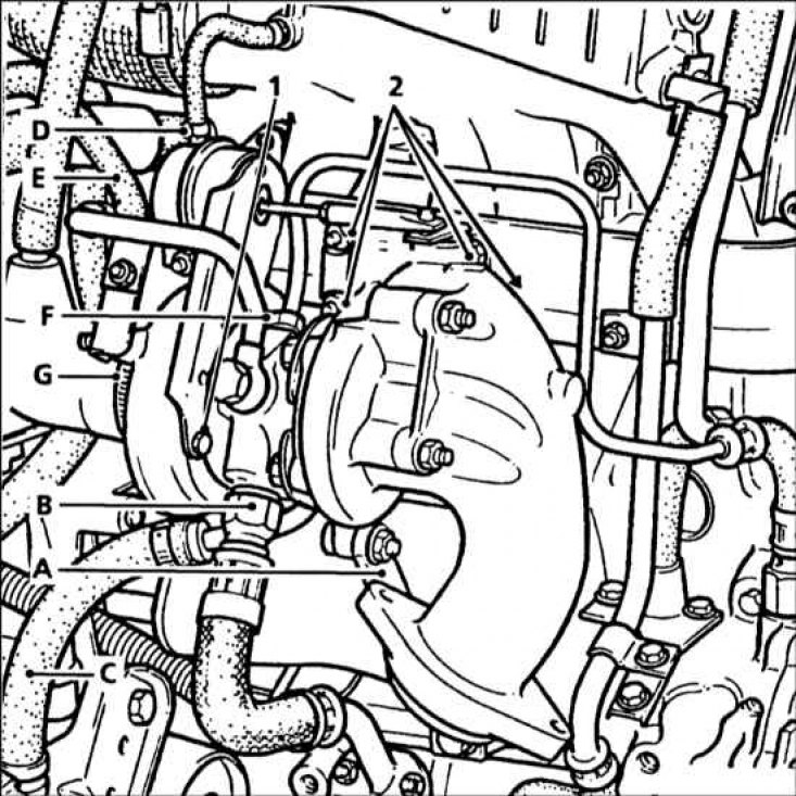


The drain bolts and nuts securing the turbocharger to the manifold are marked:

The drain bolts and nuts securing the turbocharger to the manifold are marked:
A - Bottom bracket; B - Oil drain pipe coupling; C - Lower turbocharger cooling hose; E - Upper turbocharger cooling hose; F - Oil feed pipe coupling


Removal


1. While the engine is still hot, treat the turbocharger mounting bolts with a special oil to make them easier to remove.

2. Set the handbrake, then jack up the front of the car and place it on axle stands.

3. Make sure the engine is cool enough, then, on F8Q engines, drain the cooling system as described in Chapter Maintenance.

4. Where applicable, remove the upper engine protection plate.

5. Remove the front section of the exhaust system and the muffler/converter downpipe, refer to Section General description and replacement of exhaust system components.
5. Remove the front section of the exhaust system and the muffler/converter downpipe, refer to…


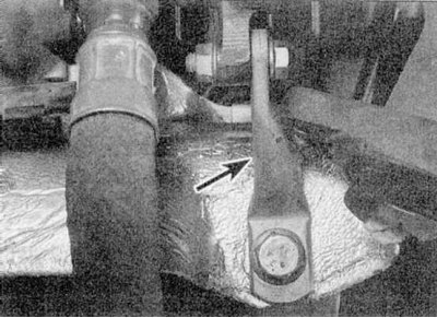
6. Working underneath the vehicle, remove the upper mounting nut and bolt, and the lower bolt, and remove the lower turbocharger bracket (refer to the illustrations).


6. Working underneath the vehicle, remove the upper mounting nut and bolt, and the lower bolt, and…


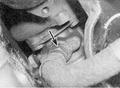
7. Unscrew the oil drain pipe coupling from the back of the turbocharger (refer to the accompanying illustration). Be prepared for oil to come out.
7. Unscrew the oil drain pipe coupling from the back of the turbocharger (refer to the accompanying…


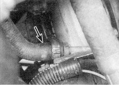
8. On models with F8Q engine, cut the clamp and disconnect the lower coolant hose from the turbocharger pipe (refer to the accompanying illustration). Be prepared for coolant to leak.

9. Working in the engine compartment, unscrew the reinforcing rod between the domes of the front suspension struts.

10. Remove the air cleaner assembly as described in Section Removal and installation the air filter housing.

11. Loosen the clamps and remove the air duct connecting the intake manifold to the intercooler.

12. Loosen the clamps and remove the air duct connecting the air cleaner to the turbocharger. Also disconnect the breather hose connecting the air duct to the intake manifold. Note the location of the clamps on the air duct.


13. Loosen the clamp and disconnect the air outlet duct (going to the intercooler) from the turbocharger.

14. Remove the nut securing the pre-glow control unit to the bulkhead and move the unit to the side without disconnecting the wiring.
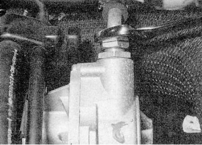
14. Remove the nut securing the pre-glow control unit to the bulkhead and move the unit to the side…


15. Loosen the nut and disconnect the vacuum tube from the vacuum pump (refer to the accompanying illustration).
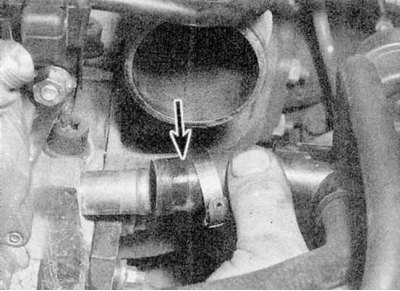
15. Loosen the nut and disconnect the vacuum tube from the vacuum pump (refer to the accompanying…


16. On models with F8Q engine, disconnect the coolant hose from the rear of the cylinder head and move the hose to the side (refer to the accompanying illustration).
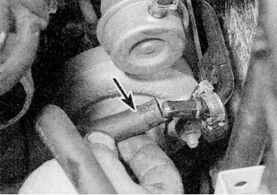
16. On models with F8Q engine, disconnect the coolant hose from the rear of the cylinder head and…


17. Disconnect the upper hose of the turbocharger cooling system in the same way (refer to the accompanying illustration).
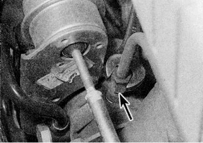


17. Disconnect the upper hose of the turbocharger cooling system in the same way (refer to the…


18. Loosen the nut and disconnect the oil feed pipe from the top of the turbocharger (refer to the accompanying illustration). You may need to remove the bypass bracket to gain access to the union nut.
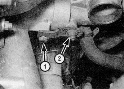
18. Loosen the nut and disconnect the oil feed pipe from the top of the turbocharger (refer to the…


19. Remove the bolt and nut of the bracket securing the air duct to the turbocharger and remove the bracket (refer to the accompanying illustration).
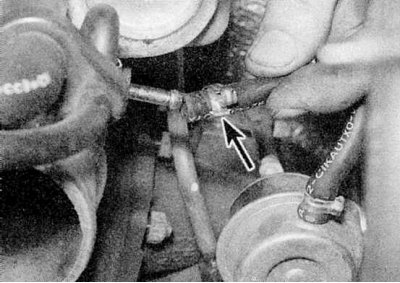
19. Remove the bolt and nut of the bracket securing the air duct to the turbocharger and remove the…


20. Disconnect the boost pressure pipe from the intake manifold (refer to the accompanying illustration).
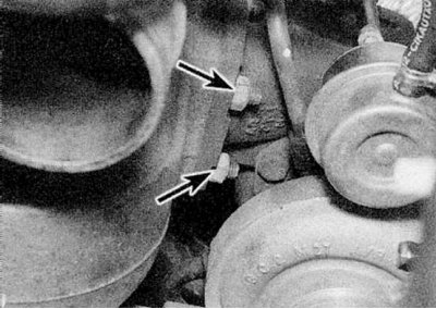


20. Disconnect the boost pressure pipe from the intake manifold (refer to the accompanying…


21. Unscrew the four nuts securing the turbocharger to the manifold, and remove the turbocharger from the studs on the manifold (refer to the accompanying illustration). To improve access to the nuts, unscrew the exhaust manifold from the turbocharger.
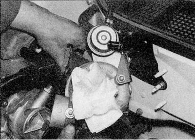
21. Unscrew the four nuts securing the turbocharger to the manifold, and remove the turbocharger…


22. Remove the turbocharger upwards, passing it under the vacuum pump, and then out between the vacuum pump and the expansion tank (refer to the accompanying illustration).

23. If a new turbocharger is being installed, remove the coolant pipes and exhaust manifold from the old unit and reinstall them on the new unit. Use new nuts when installing the exhaust manifold, and new seals when installing the coolant pipe.

Installation


1. Install in reverse order, but replace any damaged clamps and use new turbocharger-to-exhaust manifold mounting nuts, which should be tightened to the specified torque Specifications force. Tighten the union nuts of the oil supply and return pipes to the turbocharger to the specified Specifications force. Where applicable, the exhaust manifold must be installed on the turbocharger using new nuts. Fill the cooling system as described in Chapter Maintenance.


2. Finally, before starting the engine, the following steps must be performed.
  • a) Disconnect the wiring from the fuel shut-off valve on the fuel pump and insulate the connector.
  • b) Crank the engine with the starter until the pressure indicator lamp on the instrument panel goes out (this may take a few seconds).
  • c) Connect the wiring to the fuel cut-off valve, then start the engine.
  • d) Let the engine idle and check the turbocharger for oil and coolant leaks. Repair any problems.

3. After starting the engine, check the engine oil level and top up if necessary.
This article is available on: russian, bulgarian, belarusian, ukrainian, serbian, croatian, romanian, polish, slovak, hungarian
Article has been reviewed by editor: Fedoseev Denis
Share with friends:
Previous
Megane 1: Fuel system (diesel)
Next

Turbocharger — Description and Precautions
Checking and adjusting idle speed and deceleration speed
Removal and installation the intake manifold and exhaust manifold
Checking, removing and installing injectors
Checking and adjusting the injection timing
Turbocharger inspection and maintenance
Removal and installation the intercooler (turbocharged models)
General description and replacement of exhaust system components
Other articles on other Renault models

➽ Turbocharger — removal, installation and testing Renault Duster 1 (2009-2017)
➽ Turbocharger cooler outlet air duct (H4J engine) Renault Fluence 1 (2009-2020, petrol)
➽ Pneumatic actuator of turbocharger boost pressure regulator Renault Laguna 2 (2001-2007)
➽ Turbocharger oil line (K9K diesel engine only) Renault Logan 2 (2012-2020)
➽ Turbocharger — design description Renault 19 (1988-1996)
Link to this article in different formats
Reviews and comments of visitors
No comments yet


Add two numbers 30 + 49


Megan 2 (2002-2009, petrol) 
  • User manual
  • Introduction to manual
  • Controls and instruments
  • Salon equipment
  • Operation and driving
  • Maintenance and care
  • Power unit
  • Engine repair
  • Fuel system
  • Injection system
  • Intake and exhaust system
  • Starting and charging system
  • Cooling system
  • Decreased toxicity
  • Transmission
  • Clutch
  • Mechanical gearbox
  • Automatic gearbox
  • Wheel drive mechanism
  • Chassis, running gear
  • Suspension and wheels
  • Steering
  • Brake system
  • Body and interior
  • Exterior (external elements)
  • Interior (internal elements)
  • Doors, locks and windows
  • Heating and air conditioning
  • Electrical equipment
  • Equipment and devices
  • Headlights and lighting
  • Electrical circuits
Megane 1 (1995-2002) 
  • General information
  • User manual
  • Maintenance
  • Power unit
  • Petrol engines 1.4/1.6 l
  • Petrol engines 2.0 l
  • Diesel engines 1.9 l
  • Overhaul of engines
  • Cooling system
  • Fuel system (petrol)
  • Fuel system (diesel)
  • Decreased toxicity
  • Charge and launch systems
  • Ignition system (petrol)
  • Preheat system (diesel)
  • Transmission
  • Clutch
  • Mechanical gearbox
  • Automatic gearbox
  • Drive shafts
  • Chassis, running gear
  • Brake system
  • Car suspension
  • Steering
  • Body and interior
  • Exterior (external elements)
  • Interior (internal elements)
  • Doors, locks and windows
  • Electrical equipment
  • Equipment and devices
  • Electrical circuits
RenaultBook.ru © 2018–2026 | Mobile version | News and articles | Sitemap: EN BG BY UA RS HR RO PL SK HU | Administration | Site search | Bookmark
Duster 1 (2009-2017) | Fluence 1 (2009-2020, petrol) | Kangoo 1 (1997-2007) | Laguna 2 (2001-2007) | Logan 1 (2004-2012, petrol) | Logan 2 (2012-2020) | Megane 1 (1995-2002) | Megan 2 (2002-2009, petrol) | Sandero 1 (2007-2012, petrol) | Scenic 1 (1996-2003) | Symbol 1 (1999-2008, petrol) | Symbol 2 (2008-2013, petrol) | Renault 19 (1988-1996) | Espace I and II (1984-1996) | Espace III (1996-2002) | Clio 1 (1990-1998) |
We want your visit to be comfortable 😌 and use cookies 🍪 to do so.