



Removal and installation fuel injectors
Removal fuel injectors
1. Disconnect the negative battery terminal.
2. Remove the high pressure fuel line between the fuel rail and the injector(s).
3. Clean the return fuel line connectors on the fuel injectors.
Caution: To avoid corrosion or damage, take steps to protect surfaces that may come into contact with leaking fuel.
4. Disconnect the return fuel lines (1) from the fuel injectors.
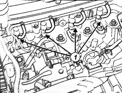
5. Install suitable plugs on the return ports of the fuel injectors. Also plug the openings of the return fuel lines.
Note: If one or more fuel injectors are to be reused, the position of the injectors relative to their respective cylinders must be marked before removal. After removal, place the injectors in a sealed bag.
6. Loosen the bolt (2) of the bracket of the corresponding fuel injector.
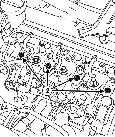
7. Remove the fuel injector bracket.
8. Remove the spring washer located at the bottom of the fuel injector.
Note: If the fuel injector is stuck and cannot be removed, turn it by the flat surfaces of the bracket with an open-end wrench.
9. Install a suitable plug onto the end of the fuel injector.
Cleaning fuel injectors
Attention:
- It is strictly forbidden to clean fuel injectors with a metal brush, sandpaper, or ultrasound.
- When working, use leak-resistant nitrile gloves.
1. Soak the fuel injectors in a special cleaning agent.
2. Clean the fuel injectors using lint-free cloths or a toothbrush.
3. Dry the fuel injectors.
Cleaning fuel injector seats
1. Install the 11 mm nozzle (3) (the outer diameter of the nozzle is equal to the diameter of the washer) on the extension cord (4).
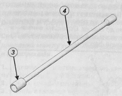
2. Wrap the cleaning cloth around the extension cord with the attachment.
3. Dampen a cleaning cloth with the cleaning agent.
4. Insert the wrapped extension cord with the nozzle into the fuel injector socket.
5. Clean the fuel injector socket.
Note: Turn the extension with the nozzle into the nozzle socket.
6. Remove the cleaning cloth from the slot.
7. Insert a large Phillips screwdriver (more than 8 mm) into the fuel injector socket to block the opening into the combustion chamber.
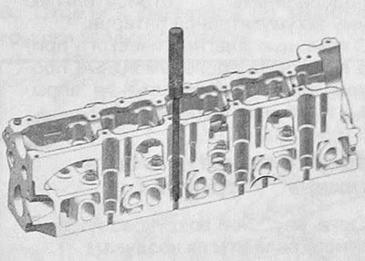
8. Blow out the remaining scale with compressed air.
9. Remove the screwdriver and repeat the cleaning procedure with the cloth as described above.
Installing fuel injectors
Attention:
- Remove plugs from components and remove components from packaging immediately before installing the component.
- Be sure to replace the fuel injector seals with new ones after each removal.
1. Clean the fuel injectors and their seats in the cylinder head.
2. Install a new spring washer.
3, Install the fuel injector.
4. Install the fuel injector bracket.
5. Install the fuel injector bracket bolt.
Note: If the fuel injector is reused, install it in the same position it was in before removal. Pay attention to the alphanumeric designation (5) of the fuel injector.
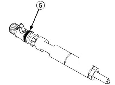
6. Tighten the fuel injector bracket bolt to 28 N·m.
7. Remove the plug from the fuel injector return port.
8. Install the high pressure fuel line between the fuel rail and the injector.
9. Connect the return fuel line to the injector.
Note: Install all other fuel injectors in the same manner
10. Make sure there are no fuel leaks.
11. Connect the negative battery terminal.
12. Using the diagnostic tool, perform post-repair procedures for the injection control unit and fuel injectors.
Checking the tightness of fuel injectors
1. Remove the intercooler intake duct.
2. Remove the fuel rail protection.
3. Connect the four clear hoses of the fuel injector leak tester to the return ports of the fuel injectors.
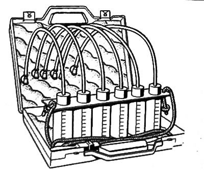
Note: The hoses must be installed on the return fittings of the fuel injectors with tension. If the hose is deformed and is installed too loosely on the fitting, it is necessary to cut off the stretched part of the hose to ensure a tight fit.
4. Insert the ends of the connected transparent hoses into the measuring cups of the device.
5. Install the intercooler air outlet duct clamp.
6. Clamp the intercooler air outlet duct onto the damper valve.
7. Connect the boost pressure sensor connector.
8. Install the turbocharger air outlet duct clamp.
9. Clamp the intermediate air duct between the turbocharger and the intercooler onto the turbocharger outlet port.
10. Connect the independent starter.
11. Connect the independent starter to the vehicle's on-board network.
12. Connect the diagnostic device.
13. Run command VP036: "Fuel supply cut-off" ("Fuel supply inhibition").
14. Turn on the starter for 15 seconds.
15. Make sure that the amount of fuel returned from each injector is more than 15 ml.
16. Repeat the procedure twice with an interval of 30 seconds between each starter activation.
17. Run command VP037: "Stop fuel cutoff" ("Stop fuel supply inhibition").
18. Disconnect the diagnostic tool.
19. Disconnect the independent starter.
20. Further actions are performed in reverse order.
The original can be found on the website: Renaultbook.ru