



Removal and installation the high-pressure fuel line between the fuel pump and the rail
Removal the high pressure fuel line
1. Disconnect the negative battery terminal.
2. Remove the turbocharger air outlet duct.
3. Remove the oil dipstick.
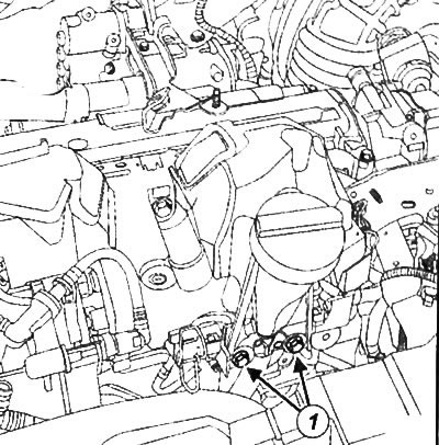
4. Loosen the bolts (1) and move the dipstick guide to the side.
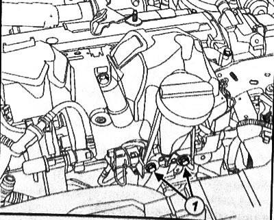
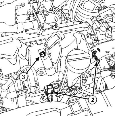
5. Unhook the fasteners (2) of the fuel rail cover.
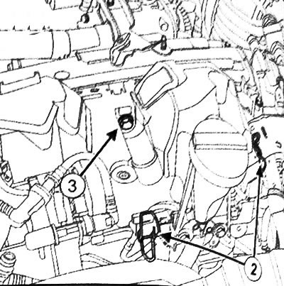
6. Loosen the bolt (3) and remove the protective cover of the fuel rail.
7. Disconnect the connector (4) of the fuel rail pressure sensor.
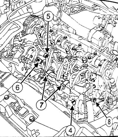
8. Disconnect the fuel temperature sensor connector (5).
9. Disconnect the connector (6) of the flow control solenoid valve.
10. Disconnect the connectors of all glow plugs.
11. Disconnect the connectors of all fuel injectors.
12. Disconnect the clamps (7) of the injection control wire.
13. Unscrew the nut (8) from the injection control wiring bracket.
14. Move the electrical wiring to the side
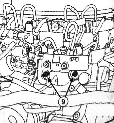
15. Unscrew the nuts (9) and remove the fuel rail protection.
16. Clean the high pressure fuel line connectors between the fuel pump and the rail.
Caution: To avoid corrosion or damage, it is necessary to take measures to protect surfaces that may come into contact with leaking fuel.
17. Unscrew the nuts (10) of the fuel rail.
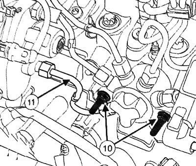
Caution: When loosening the high-pressure fuel lines, be sure to hold the intermediate joint with a wrench. Be careful not to damage the return fuel line of the fuel injectors.
18. Remove the high-pressure fuel line (11) between the high-pressure fuel pump and the fuel rail.
19. Place suitable plugs on the high pressure fuel pump and fuel rail port openings.
Installing a high pressure fuel line
Attention:
- Before installing a new high-pressure fuel line, it is necessary to lightly lubricate the threads of the nut with oil from the tube supplied in the new repair kit.
- Be careful not to let oil get inside the fuel line.
- Do not lubricate high pressure fuel lines supplied without a tube - these fuel lines are already lubricated.
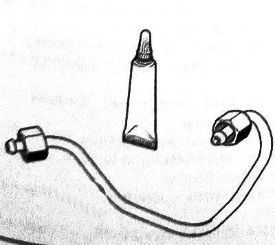
(View the original source on this resource: «www.RENAULTBOOK.ru»)
Attention:
- Remove plugs from components and remove components from packaging immediately before installing the component.
- Be sure to replace the high-pressure fuel line between the fuel pump and the rail with a new one after each removal.
1. Remove the plugs from the high pressure fuel pump and fuel rail ports.
2. Install a new high-pressure fuel line between the fuel rail and the high-pressure fuel pump.
3. Without tightening, screw the high-pressure fuel line nuts by hand between the fuel rail and the high-pressure fuel pump, starting from the fuel rail side.
4. Using a special wrench for tightening the fuel line connecting nuts, tighten the high-pressure fuel line nuts between the fuel rail and the high-pressure fuel pump to a torque of 28 N·m.
5. Tighten the fuel rail mounting nuts to a torque of 28 Nm.
6. Install the fuel rail protection.
7. Install the injection control wiring.
8. Install the injection control wiring bracket nut.
9. Hook up the wiring clamps.
10. Connect the connectors of all fuel injectors.
11. Connect the connectors of all glow plugs.
12. Connect the fuel flow control solenoid valve connector.
13. Connect the fuel temperature sensor connector.
14. Connect the fuel rail pressure sensor connector.
15. Install the protective cover of the fuel rail and tighten its mounting bolt.
16. Hook on the protective cover of the fuel rail.
17. Install the dipstick guide tube and tighten the mounting bolts.
18. Install the oil dipstick.
19. Install the turbocharger air outlet duct.
20. Connect the battery.
21. Fill the system with fuel using a hand priming pump (with automatic air removal).
22. Make sure there are no fuel leaks.
Removal and installation high-pressure fuel lines between the fuel rail and injectors
Removal high pressure fuel lines between the fuel rail and injectors
1. Disconnect the negative battery terminal.
2. Remove the engine cover.
3. Remove the turbocharger air outlet duct.
4. Remove the oil dipstick.
5. Loosen the bolts (1) and move the dipstick guide to the side.
6. Unhook the fasteners (2) of the fuel rail protective cover.
7. Clean the high-pressure fuel line connectors between the fuel rail and the injectors.
Attention:
- When loosening the high-pressure fuel lines, be sure to hold the intermediate joint with a wrench. Be careful not to damage the return fuel line of the fuel injectors.
- To avoid corrosion or damage, measures must be taken to protect surfaces that may come into contact with leaking fuel.
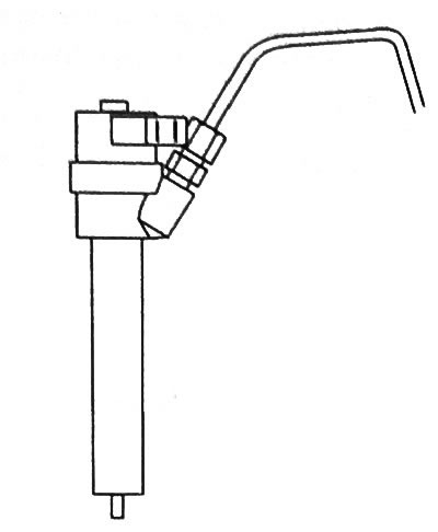
If it is necessary to remove individual high pressure fuel lines
8. Using the special tool (Mot. 1566), loosen the connecting nuts of the high-pressure fuel lines between the fuel rail and the injectors.
9. Loosen the connecting nuts of the high-pressure fuel lines between the fuel rail and the injectors on the fuel rail side.
10. Unscrew the connecting nuts of the high-pressure fuel lines between the fuel rail and the injectors from the injector side.
11. Remove the high pressure fuel line.
12. Install the appropriate plugs on the fuel rail and injector ports.
If it is necessary to remove high-pressure fuel lines in one package
13. Disconnect the connector (4) of the fuel rail pressure sensor.
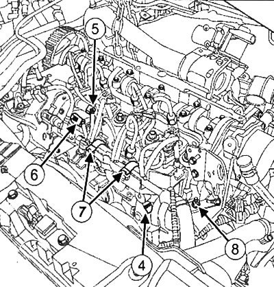
14. Disconnect the fuel temperature sensor connector (5).
15. Disconnect the connector (6) of the flow control solenoid valve.
16. Disconnect the connectors of all glow plugs.
17. Disconnect the connectors of all fuel injectors.
18. Disconnect the clamps (7) of the injection control wiring.
19. Unscrew the nut (8) from the injection control wiring bracket.
20. Move the electrical wiring to the side.
21. Unscrew the nuts (9) and remove the fuel rail protection.
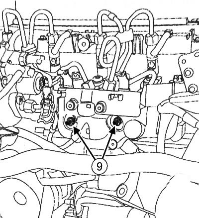
22. Unscrew the nuts (10) of the fuel rail.
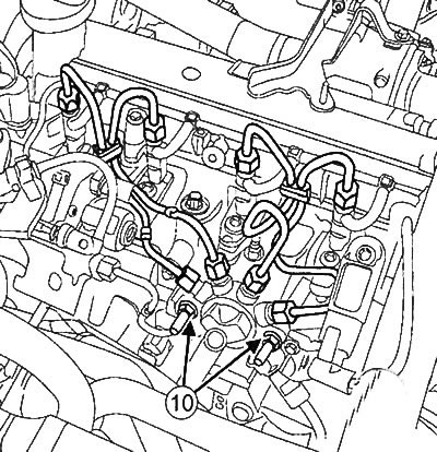
23. Using the special tool (Mot. 1566), loosen the connecting nuts of the high-pressure fuel lines between the fuel rail and the injectors.
24. Loosen the connecting nuts of the high-pressure fuel lines between the fuel rail and the injectors on the fuel rail side.
25. Unscrew the connecting nuts of the high-pressure fuel lines between the fuel rail and the injectors on the injector side.
26. Remove the high pressure fuel lines.
27. Install the appropriate plugs on the fuel rail and injector ports.
Installation of high pressure fuel lines between the fuel rail and injectors
Attention:
- Before installing a new high-pressure fuel line, it is necessary to lightly lubricate the threads of the nut with oil from the tube supplied in the new repair kit.
- Be careful not to let oil get inside the fuel line.
- Do not lubricate high pressure fuel lines supplied without a tube - these fuel lines are already lubricated.
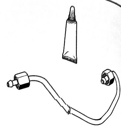
Attention:
- Remove plugs from components and remove components from packaging immediately before installing the component.
- Be sure to replace the high-pressure fuel lines between the fuel rail and the injectors with new ones after each removal.
1. Remove the plugs from the fuel rail ports and injectors.
2. Install new high-pressure fuel lines between the fuel rail and the injectors.
3. Without tightening, screw the high-pressure fuel line nuts by hand between the fuel rail and the high-pressure fuel pump, starting from the fuel rail side.
4. Using a special wrench for tightening the fuel line connecting nuts, tighten the high-pressure fuel line nuts between the fuel rail and the injectors to a torque of 28 N·m.
5. Tighten the fuel rail mounting nuts to a torque of 28 Nm.
6. Install the fuel rail protection.
7. Install the injection control wiring.
8. Install the injection control wiring bracket nut.
9. Hook up the wiring clamps.
10. Connect the connectors of all fuel injectors.
11. Connect the connectors of all glow plugs.
12. Connect the fuel flow control solenoid valve connector.
13. Connect the fuel temperature sensor connector.
14. Connect the fuel rail pressure sensor connector.
15. Install the protective cover of the fuel rail and tighten its mounting bolt.
16. Hook on the protective cover of the fuel rail.
17. Install the dipstick guide tube and tighten the mounting bolts.
18. Install the oil dipstick.
19. Install the turbocharger air outlet duct.
20. Connect the battery.
21. Fill the system with fuel using a hand priming pump (with automatic air removal).
22. Make sure there are no fuel leaks.