
Attention. It is strongly recommended to follow the sequence of adjustments.
Adjusting idle speed and idle return
Note. These adjustments must be made on a hot engine after turning on the radiator fan twice.
- Make sure the idle control lever is (1. fig. 3.15) really rests against the end of the idle speed adjustment screw (3).
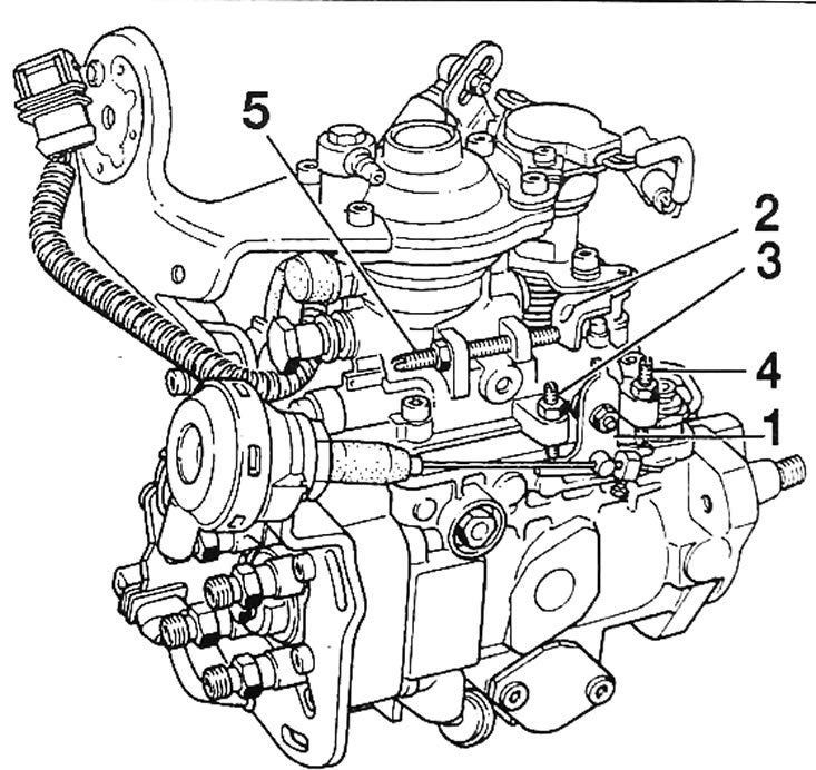
Pic. 3.15. Adjusting modes (engine G8T714 and G8T716): 1 - idle speed lever; 2 - load lever; 3 - idle speed adjustment screw; 4 - fast idle adjustment screw; 5 - screw for limiting the residual capacity
- Unscrew the residual capacity limiting screw two turns (5).
- Rotating the screw (3), adjust the crankshaft engine idle speed to 725±50 min-1
- Install a 1 mm thick feeler gauge between the end of the adjusting screw (5) residual capacity and load lever (2).
- Rotating the screw (5) limiting the remaining capacity, set the crankshaft speed 10-20 min-1 higher than the idle speed.
- Take out a 1mm thick feeler gauge. Increase the engine speed sharply several times and let it slowly return to idle.
- If necessary, use the adjusting screw to adjust the engine idle speed.
- Press and release the accelerator pedal several times while selecting mode G31* on the Renault XR 25.
Attention. Any adjustment of the residual capacity limit screw requires re-checking using the Renault XR 25.
Fast idle
Note. This adjustment must be carried out on a hot engine after previous adjustments have been made.
- Manually set the idle control lever (1) and fast idle to the end of the fast idle adjustment screw (4).
- Check that the engine speed at fast idle is stabilized at 850±25 min-1 and, if necessary, rotating the adjusting screw (4), adjust it.
Note. To adjust the fast idle speed on cars. equipped with air conditioning, it is enough to connect a pneumatic circuit to the atmosphere.
Adjusting the fast idle cable
Note. This adjustment must be carried out on a hot engine after previous adjustments have been made.
- Make sure that the idle speed lever rests against the end of the adjusting screw.
- Keeping the cable taut, secure it at a distance (X. fig. 3.16) from the idle lever, which is correspondingly equal to:
- version without air conditioning system: X = 5±1 mm;
- version with air conditioning system: X = 2±1 mm.
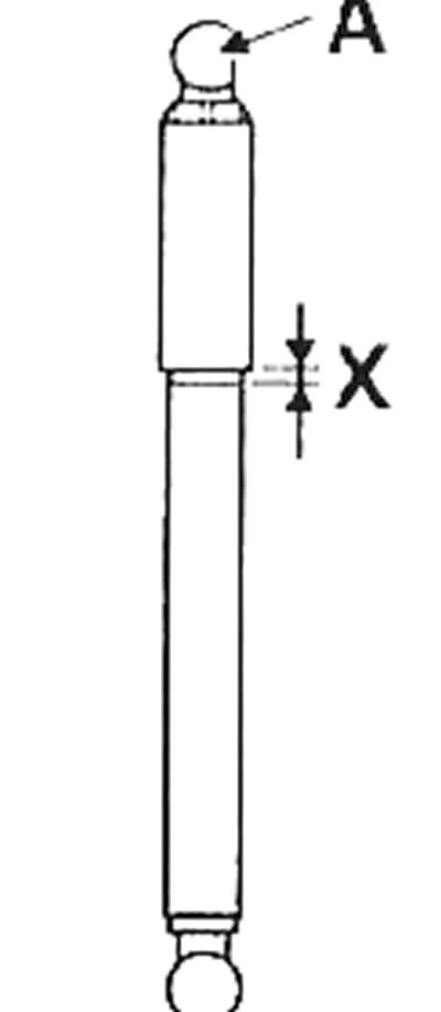
Pic. 3.16. Deceleration damper: A - upper shock absorber hinge; X - adjustment gap
Deceleration damper
- The deceleration damper smoothly transfers force from the accelerator pedal to the load lever.
- After the previous adjustments, it is necessary to adjust the length of the deceleration damper. Lever arm (1, fig. 3.15) should rest against the adjusting screw (3).
- Using paint applied to the shock absorber body, mark the position of the upper part of the shock absorber.
- Press the upper shock absorber hinge until the adjustment gap is X = 2 mm (pic. 3.16).