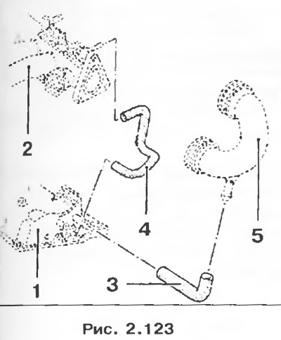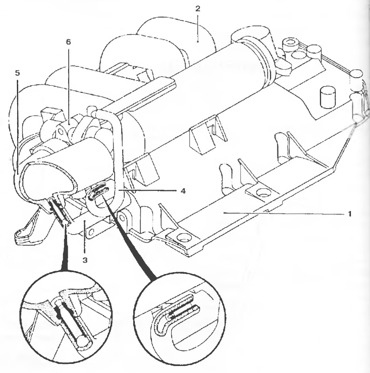
Pic. 2.122. Scheme of the oil vapor recovery system:
1 - Cylinder head cover;
2 - Collector;
3 - The pipeline of oil vapor recovery systems connected to the over-throttle space of the throttle valve (the circuit is used for medium and heavy loads);
4 - The pipeline of the oil vapor recovery system, connected to the throttle space of the throttle valve;
5 - Air duct;
6 - Throttle valve block.
Examination
To ensure the normal operation of the emission control system, the oil vapor recovery system must be kept clean and in good condition.