



Contents: Removal 🠛 Installation 🠛
The catalytic converter becomes very hot when the engine is running, so you should never stop in a place where flammable materials could accidentally come into contact with the hot converter and ignite. Under certain conditions, these materials could catch fire.
Attention!
- - The section from the exhaust manifold to the neutralizer inclusive must be sealed.
- - All removed gaskets must be replaced without fail (especially the neutralizer flange gasket).
- - When removing and installing the neutralizer, protect it from impacts that may damage it.
Removal
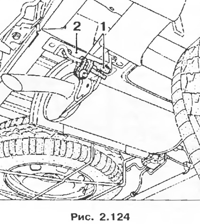
1. The exhaust system components are suspended on the underbody using rubber-metal cushions 1. As a rule, they can be disconnected without using tools, manually, by lifting the exhaust pipe. However, in some cases, it is necessary to unscrew the bracket mounting bolts 2 to make it easier to remove the suspension cushions.
2. The exhaust pipe is a non-separable unit, i.e. there are no pipe joints from the inlet to the catalytic converter or front muffler to the outlet from the main muffler. In this regard, in order to replace one of the pipeline elements during maintenance, it is necessary to cut the exhaust pipe.
To do this you need:
- accurately define the cutting area;
- use cutting tool Mot. 1199-01;
- install the repair coupling.
3. The cutting zone is marked by two blows of the core on the exhaust pipe.
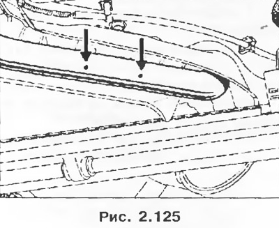
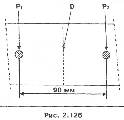
Maximum (depending on the engine type) there are two cutting zones on the exhaust pipe, which are located between the neutralizer and the resonator and between the resonator and the main muffler. The distance between these two marks is 90 mm. To cut the pipe, it is necessary to draw a line D in the middle between these marks (P1 and P2).
Attention! To cut exhaust pipes you need to have tool Mot. 1199-01; this tool allows you to cut pipes with wall thickness up to 2 mm.
Installation
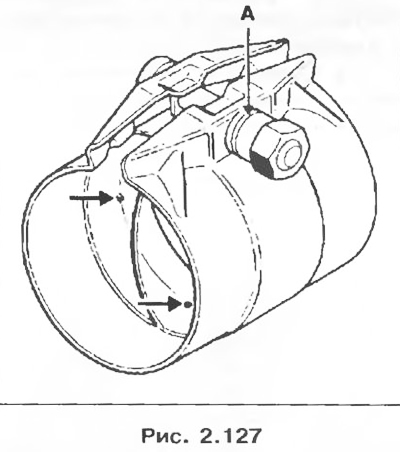
1. To avoid exhaust gas leakage, it is very important to install the coupling on the exhaust pipes correctly, i.e. the pipe must enter the coupling until it rests against the internal protrusions.
Note: There are two diameter couplings:
- 50 mm;
- 45 mm.
You should start by installing the coupling on the used part of the pipe, then adjust the diameter of the coupling hole by carefully tightening it.
2. Check the position of the pipe relative to the stops.
3. Install the new pipe section.
4. Before installing the coupling on the pipe, you can apply mastic to the inner surface of the coupling to prevent leakage of exhaust gases.
(Mastic for exhaust systems, catalog number: 77 01 421 161 SODICAM).
Attention! The bolt and nut used to secure the coupling must be oriented strictly vertically to avoid contact with the underbody. The installed coupling cannot be reused.
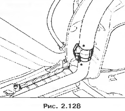
5. The coupling nut has a groove A, which serves to determine the correct tightening torque. During tightening, when the groove is compressed, a characteristic sound is heard, which indicates that the nut is tightened with a torque of 25 Nm.
Attention! Make sure:
- - that the exhaust system pipeline does not come into contact with the underbody anywhere;
- - all heat-reflecting shields of the exhaust system are present and securely fastened;
- - that both cutting zone marks are precisely aligned.
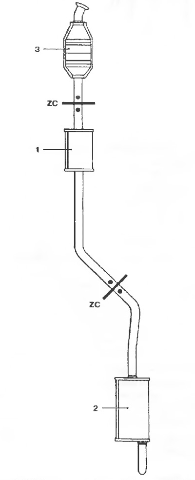
Figure 2.129. Exhaust system piping and location of cutting zones:
1 - Front muffler;
2 - Main muffler;
3 - Catalytic converter;
ZC - Pipe cutting zone.