
Note (pic. 2.1). The opening pressure of the safety valve in the plug of the expansion tank is 1.2 bar (cork brown).
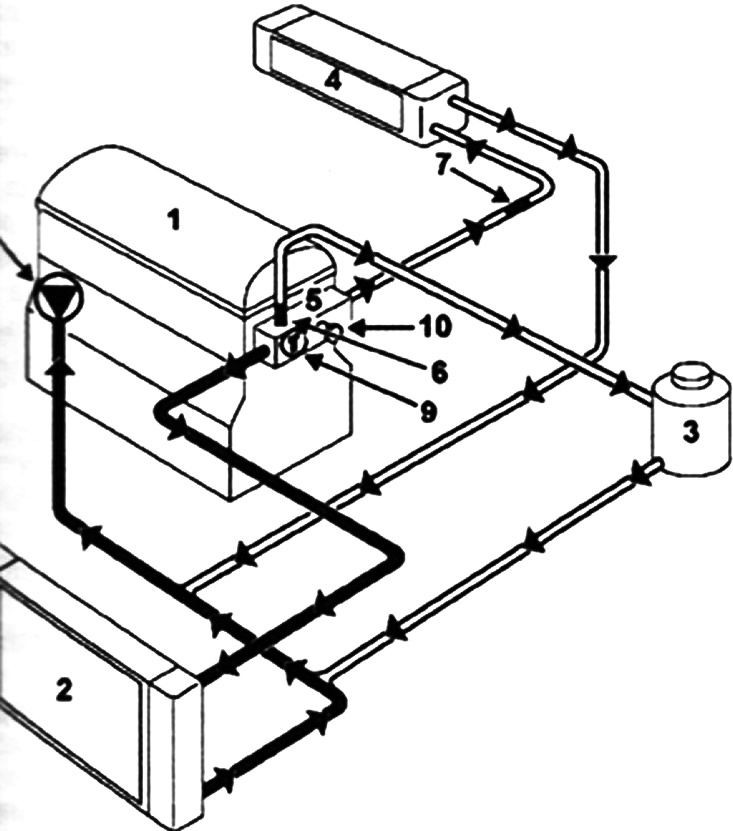
Pic. 2 1. Functional diagram of the cooling system (engines K4M, F4R, F4P - cars with MKL): 1 - engine, 2 - radiator; 3- "hot" tank with degassing after the thermostat; 4 - heater radiator; 5 - thermostat holder; 6 - branch pipe with a diameter of 0.3 mm; 7 - branch pipe with a diameter of 0.85 mm; 8 - water pump; 9 - thermostat; 10 - air vent valve
Note (pic. 2.2). The opening pressure of the safety valve in the plug of the expansion tank is 1.2 bar (cork brown).
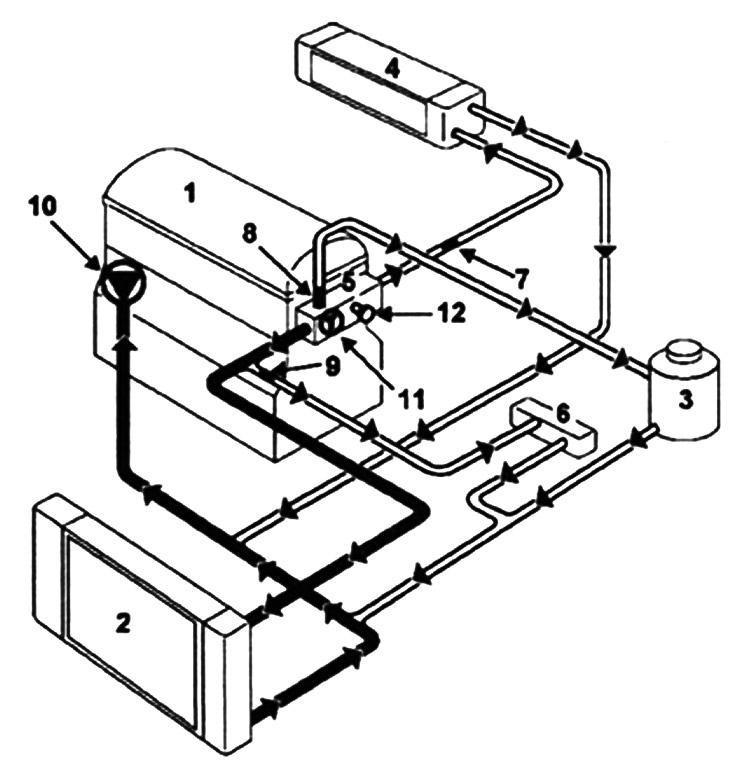
Pic. 2.2. Functional diagram of the cooling system (engines K4M, F4R. F4P - vehicles with automatic transmission): 1 - engine; 2 - radiator; 3- «hot» barrel with degassing after the thermostat; 4 - heater radiator; 5 - thermostat holder; 6 - oil-water cooler of automatic transmission; 7 - branch pipe with a diameter of 0.3 mm; 8 - branch pipe with a diameter of 0.85 mm; 9 - branch pipe with a diameter of 010 mm; 10 - water pump; 11 - thermostat; 12 - valve for air removal
Note (pic. 2.3). The opening pressure of the safety valve in the plug of the expansion tank is 1.2 bar (cork brown).
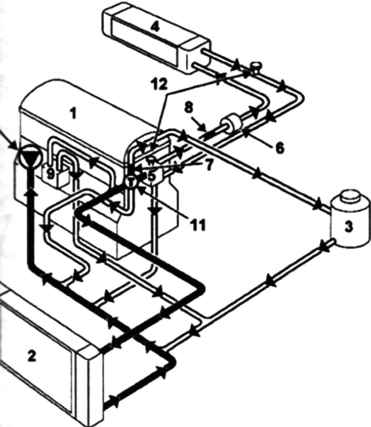
Pic. 2.3. Functional diagram of the cooling system (F9Q engines): 1 - engine; 2 - radiator; 3- "hot" tank with degassing after the thermostat; 4 - heater radiator; 5 - thermostat holder; 6 - block of immersion heaters (if they are); 7 - branch pipe with a diameter of 0.3 mm; 8 - branch pipe with a diameter of 0.85 mm; 9 • - oil-water cooler; 10 - water pump; 11 - thermostat. 12 - valve for air removal
Note (pic. 2.4). The opening pressure of the safety valve in the plug of the expansion tank is 1.2 bar (cork brown).
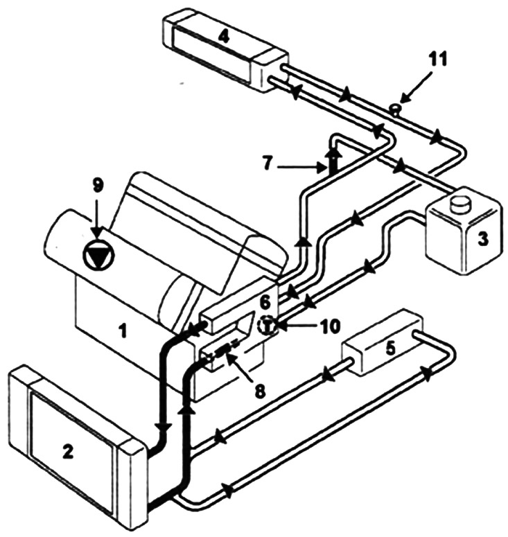
Pic. 2.4. Functional diagram of the cooling system (L7X engines): 1 - engine; 2 - radiator; 3- «hot» tank with constant degassing; 4 - heater radiator; 5 - oil-water cooler. 6 - thermostat block. 7 - branch pipe with a diameter of 0.3 mm; 8 - branch pipe with a diameter of 0.16 mm; 9 - water pump. 10 - double-circuit thermostat; 11 - air vent valves
Note (pic. 2.5). The opening pressure of the safety valve in the plug of the expansion tank is 1.4 bar (cork brown).
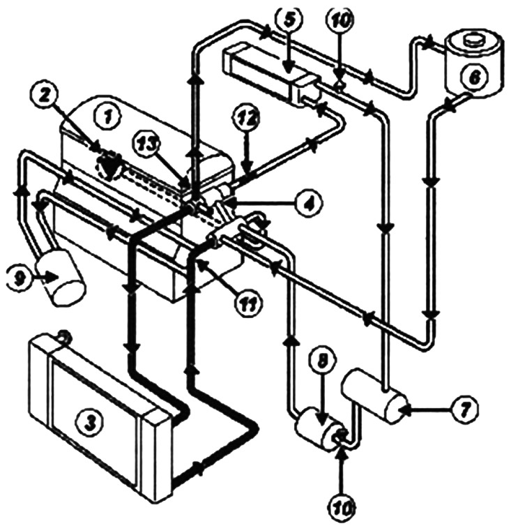
Pic. 2.5. Functional diagram of the cooling system (G9T engines, with PK6 gearbox): 1 - engine: 2 - water pump; 3 - radiator; 4 - thermostat. 5 - heater radiator; 6 - expansion tank; 7 - exhaust gas cooler; 8 - body of immersion heaters; 9 - oil-water cooler; 10 - plug for air removal; 11 - branch pipe with a diameter of 14 mm; 12 - branch pipe with a diameter of 7.5 mm; 13 - branch pipe with a diameter of 3 mm
Note (pic. 2.6). The opening pressure of the safety valve in the plug of the expansion tank is 1.4 bar (cork brown).
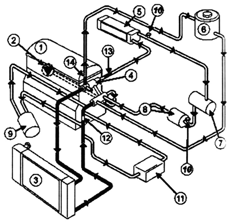
Pic. 2.6. Functional diagram of the cooling system (G9T engines, with SU1 gearbox): 1 - engine; 2 - water pump 3 - radiator of the engine cooling system. 4 - thermostat; 5 - heater radiator; 6 - expansion tank 7 - exhaust gas cooler; 8 - body of immersion heaters; 9 - water-oil cooler of the engine; 10 - plugs for air removal; 11 - oil-water cooler of the gearbox; 12 - branch pipe with a diameter of 14 mm; 13 - branch pipe with a diameter of 7.5 mm; 14 - branch pipe with a diameter of 3 im