
Sensors
The engine management system uses two types of sensors called «active» or «passive» which differ in their internal functioning caused by their design. Active sensors operate autonomously and do not require external power supply. On the contrary, passive sensors require an external power supply to produce a signal. The electronic control unit receives information from the following sensors:
- air pressure in the intake manifold;
- angular position of the throttle valve;
- an inductive speed and crankshaft position sensor located near the flywheel ring gear and generating a sinusoidal voltage proportional to the engine operating mode. In order for the sensor to generate a specific crankshaft position signal, two teeth are missing on the ring gear. - the camshaft position sensor for recognizing the cylinder at the beginning of the intake stroke, located on the left side of the cylinder head, sends a signal that, in accordance with the signal sent by the mode/crankshaft position sensor, allows the control unit to calculate the cylinder located at the beginning of the intake stroke and determine the valve timing and ignition timing in the corresponding cylinder;
- the concentration of oxygen in the exhaust gases, located in the exhaust pipe and generating a characteristic galvanic charge, which is an indicator of the oxygen content in the exhaust gases;
- a piezoelectric knock sensor installed on the cylinder head and reacting to the high-frequency vibrations of the cylinder block that occur during detonation and transforming them into electrical signals, on the basis of which the control unit shifts the ignition timing towards retardation;
- coolant temperature with negative temperature coefficient (CTN);
- temperature of air entering the engine with a negative temperature coefficient (CTN);
- speed of the vehicle installed in the gearbox;
- on/off the air conditioning system: based on its signal, the control unit, depending on the engine operating mode, allows or prohibits the activation of the air conditioning compressor clutch;
- oil pressure in the hydraulic drive of the power steering transmitting a signal to the engine control unit, if the pressure exceeds a certain value, the engine speed increases;
- battery voltage, based on the signal from which the control unit adjusts the crankshaft speed at idle and compensates for the voltage drop when a large number of consumers are turned on, when the battery is not charged much.
Actuators
The electronic unit controls the following devices
- The fuel pump relay supplies voltage to pin 52 of the engine control unit connector and powers the fuel pump, activated carbon canister solenoid valve, idle speed control, cylinder recognition sensor at the beginning of the intake stroke, Lambda sensor and injectors;
- idle speed regulator, which changes the cross-section of the channel for supplying air bypassing the throttle valve, as a result of which the required crankshaft speed is maintained at idle;
- injectors, the opening time of which affects the amount of fuel injected;
- ignition coils, to which the ignition signal is transmitted by the control unit through the switch. Sparking occurs simultaneously on two spark plugs of those cylinders whose pistons are in the TDC area, by breaking the chain «masses» corresponding ignition coil. The two ignition coils each have two power contacts and are controlled separately by the injection system control unit. Injection system control unit, depending on the signals from the crankshaft position sensor, pressure sensor and other sensors. But. Basically, based on data on the load and engine speed, the optimal ignition timing is determined in accordance with the program.
- solenoid valve of the activated carbon canister mounted on the right in the rear of the engine compartment and under certain conditions
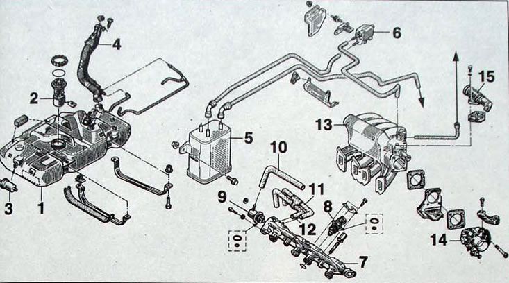
Pic. 1.12. Fuel system: 1 - fuel tank; 2 - fuel pump; 3 - fuel filter; 4 - fuel filler neck of the fuel tank; 5 - adsorber; 6 - adsorber solenoid valve; 7 - fuel line; 8 - nozzle; 9 - pressure regulator; 10 - vacuum hose; 11 - fuel supply hose; 12 - fuel return hose; 13 - intake manifold; 14 - throttle assembly; 15 - idle speed regulator
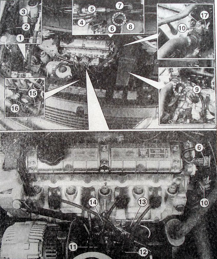
Pic. 1.13. Location of elements of the SIEMENS FENIX 5 engine management system in the engine compartment:1 - electronic control unit; 2 - canister with activated carbon adsorber); 3 - inertial shock sensor; 4 - throttle position sensor; 5 - idle speed regulator; 6 - cylinder recognition sensor at the beginning of the intake stroke; 7 - air pressure sensor; 8 - air temperature sensor; 9 - TDC mode/position sensor; 10 - coolant temperature sensor; 11 - ignition coils of cylinders 2 and 3; 12 - ignition coils of cylinders 1 and 4; 13 - interference suppression capacitor; 14 - knock sensor; 15 - oil level/temperature sensor; 16 - oil pressure sensor; 17 - indicator coolant temperature sensor in the instrument cluster
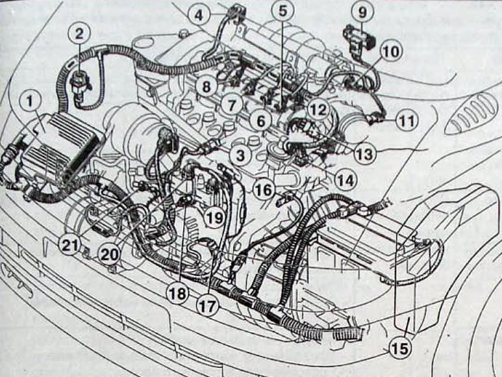
Pic. 1.14. Location of elements of the SIEMENS FENIX 5 engine management system in the engine compartment: 1 - electronic control unit; 2 - inertial shock sensor; 3 - knock sensor; 4 - solenoid valve of a canister with activated carbon; 5 - nozzle No. 1; 6 - nozzle No. 2; 7 - nozzle No. 3; 8 - nozzle No. 4; 9 - air pressure sensor; 10 - idle speed regulator; 11 - air temperature sensor; 12 - throttle position sensor; 13 - cylinder recognition sensor at the beginning of the intake stroke; 14 - coolant temperature sensor; 15 - relay and fuse block; 16 - mode/crankshaft position sensor; 17 - oil level/temperature sensor; 18 - oil pressure sensor; 19 - ignition coils of cylinders 1 and 4; 20 - ignition coils of cylinders 2 and 3; 21 - oil pressure sensor in the hydraulic power steering drive