



Contents: Removal 🠛 Installation 🠛
Removal
- Disconnect the cable from the negative battery terminal.
- Disconnect the connector from the air temperature, pressure, throttle position potentiometer and camshaft position sensors (Fig. 1.36).
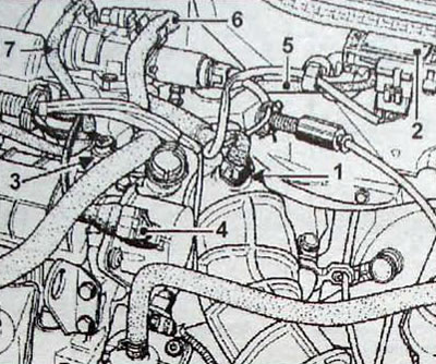
Fig. 1.36. Fuel system sensors and tubes: 1 - air temperature sensor; 2 - pressure sensor; 3 - throttle position potentiometer; 4 - camshaft position sensor; 5 - vacuum tube of pressure sensor; 6 - brake booster vacuum hose; 7 - fuel vapor discharge pipeline
- Disconnect the fuel vapor drain line, the vacuum hose from the brake booster, and the vacuum line from the pressure sensor.
- Loosen the clamp securing the air intake pipe to the throttle body.
- Unscrew the three air filter mounting nuts.
- Remove the filter and air intake pipe.
- Disconnect the oil vapor drain pipe (3. Fig. 1.37).
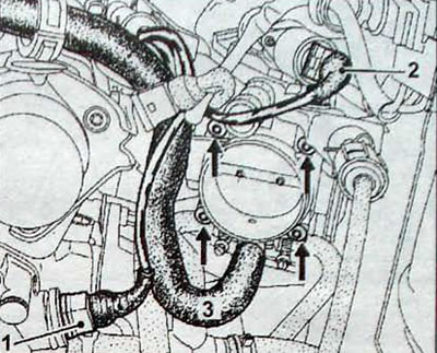
Fig. 1.37. Removing the throttle assembly: 1 - coolant temperature sensor; 2 - idle speed control valve; 3 - oil vapor discharge pipe; Arrows - throttle assembly mounting bolts
- Disconnect the connector from the coolant temperature sensor and the idle air control valve.
- Remove the four throttle assembly mounting bolts without disconnecting the coolant supply hoses to the throttle assembly.
- Remove the thermal insulation located between the throttle body and the manifold.
- Disconnect the connectors from the fuel injectors.
- Remove the wiring harness holder.
- Disconnect the wires and tubes attached to the manifold and move them to the right, towards the fuel injection system control unit.
- Disconnect the fuel supply hose with a green mark located in the area of the engine flywheel (2. Fig. 1.38)
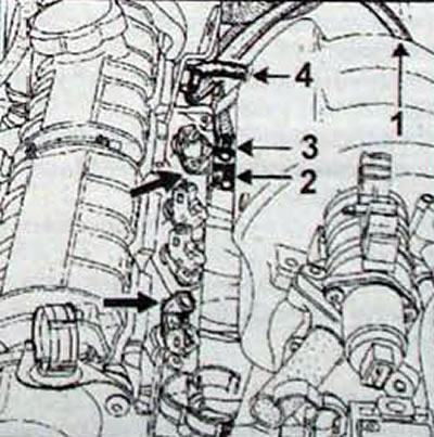
Fig. 1.38. Location of the feed (2) and return (3) fuel hoses, pressure regulator vacuum tube (4) and ground wires (1)
- Disconnect the return fuel hose with the red mark (3) located in the area of the timing drive.
- Disconnect the vacuum tube (4) from the fuel pressure regulator
- Unscrew the two nuts securing the fuel distribution line.
- Disconnect the two ground wires.
- Remove the fuel injection line by moving along the intake manifold.
Installation
- Make sure there are two plastic spacers located on the line mounting studs between the studs and the head
- Remove the glued gaskets on the thermal insulation of the throttle assembly and replace them with new ones, although it is not necessary to glue them.
- Further installation is carried out in the reverse order of removal.