



Contents: General description 🠛 C-series engine 🠛 E-Series Engines - Alternator Drive…🠛 E-Series Engines - Power Steering…🠛 E-Series Engines - Air Conditioning…🠛 E-Series Engines - A/C…🠛 F3P engines - models without power…🠛 P3P engines - models with power…🠛 P3P engines - models with air…🠛 F7P engine (with 16 valves) 🠛 D-Series Engine - Alternator Drive…🠛 D-Series Engine - Power Steering…🠛
Note: Before working around the generator, disconnect the negative battery cable.
General description
1. The type and quantity of auxiliary drive belts may vary depending on the model. To check the condition of the drive belt, proceed as follows.
2. Apply the handbrake, then jack up the front of the car and place it on axle stands. Remove the right front wheel and, where necessary, the wheel arch mudguard.
3. Check the drive belt along its entire length for cracks, splits, abrasions or damage by turning the crankshaft clockwise (see illustration).
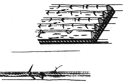
6.3 Check the drive belt for wear.
Replace the belt if it is worn or damaged.
C-series engine
Removal
4. Loosen the alternator belt tensioner nut (see illustration).
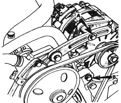
6.4 Generator Tensioner Bolt (A) and Mounting Nut (B) - C-Series Engine.
5. Loosen the alternator mounting nut (bottom), then rotate the alternator toward the engine to reduce belt tension.
6. Remove the belt from the pulleys.
Installation
7. Install the belt on the pulleys. Move the generator away from the engine and lightly tighten the nuts and bolts.
8. Tighten the drive belt as described in the following steps.
Tension
9. Correct tension of the drive belt will ensure its long service life. However, do not overtighten it as this may cause excessive wear on the generator.
10. The belt should be tensioned so that when you press firmly with your thumb at the middle of the run between the water pump pulley and the alternator pulley, it deflects approximately 4 mm (see illustration).
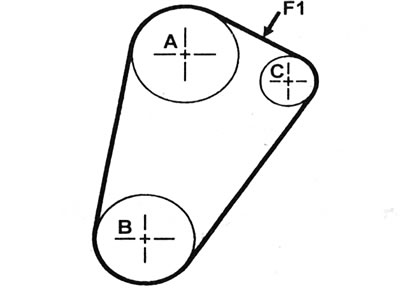
6.10 Auxiliary drive belt tension check location (P1) - C-series engine: A - Water pump pulley; B - Crankshaft pulley; C - Generator pulley; P1=4.0 mm.
11. Loosen the fasteners and move the alternator away from the engine until the correct tension is achieved, then tighten the nuts and bolts.
12. When a new belt is installed, it will stretch slightly when the engine is running. Let the engine run until the radiator fan comes on, then turn it off and check the belt tension again.
13. When the engine is warm, the belt tension should be as specified in paragraph 10.
E-Series Engines - Alternator Drive Belt
Removal
14. Where applicable, remove the power steering pump/air conditioning compressor drive belt (where available).
15. Apply the handbrake, then jack up the front of the car and place it on axle stands.
16. To improve access, remove the right wheel, then remove the wheel arch mudguard.
17. Proceed as described in points 4-6 inclusive (see illustration).
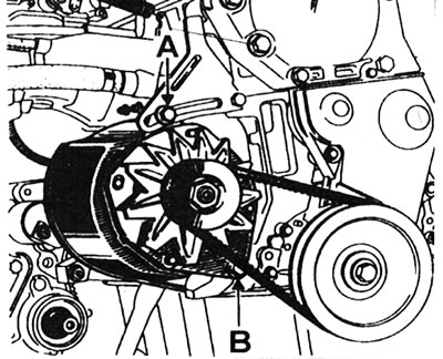
6.17 Tensioner bolt (A) and generator mounting bolt (B) - E-series engines.
Installation
18. Install the belt on the pulleys. Move the generator away from the engine and lightly tighten the nuts and bolts.
19. Tighten the drive belt as described in the following steps.
Tension
20. Proceed as described in points 15 and 16, if you have not already done so.
21. Correct tension of the drive belt will ensure its long service life. However, do not overtighten it as this may cause excessive wear on the generator.
22. The belt should be tensioned so that when you press firmly with your thumb in the middle of the run between the pulleys, it deflects by approximately 4.2 - 4.7 mm.
23. Loosen the fasteners and move the generator away from the engine until the correct tension is achieved, then tighten the nuts and bolts.
24. When a new belt is installed, it will stretch slightly when the engine is running. Let the engine run until the radiator fan comes on, then turn it off and check the belt tension again.
25. When the engine is warm, the belt should deflect by 6.2 - 7.7 mm, when using the method described in paragraph 22.
26. Finally, lower the car to the ground.
E-Series Engines - Power Steering Pump Drive Belt (models without air conditioning)
Removal
27. Loosen the upper pump mounting nut, then loosen the lock nut and the adjusting bar nut.
28. Loosen the lower pump mounting nut.
29. Loosen the adjusting nut to reduce tension, then remove the belt from the pulleys.
Installation
30. Install the belt on the pulleys. Lightly tighten the adjusting nut.
31. Tighten the drive belt as described in the following steps.
Tension
32. Correct tension of the drive belt will ensure its long service life. However, do not overtighten it as this may cause excessive wear on the pump.
33. The belt should be tensioned so that when you press firmly with your thumb in the middle of the run between the pulleys, it deflects by approximately 3.2 - 3.5 mm.
34. Turn the adjusting nut until the correct tension is achieved, then tighten the lock nut and pump mounting nut.
35. When a new belt is installed, it will stretch slightly when the engine is running. Let the engine run until the radiator fan comes on, then turn it off and check the belt tension again.
36. When the engine is warm, the belt should deflect by 5.2 - 6.7 mm, when using the method described in paragraph 33.
E-Series Engines - Air Conditioning Compressor Drive Belt (models without power steering)
Removal
37. Working in the engine compartment, loosen the two bolts securing the belt tensioner pulley bracket (see illustration).
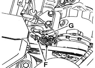
6.37 Air conditioning compressor belt tensioner pulley bracket bolts (E) and adjuster screw (C) - E-series engines without power steering.
38. Loosen the adjuster screw to reduce belt tension.
39. Remove the belt from the pulleys.
Installation
40. Install the belt on the pulleys. Lightly tighten the adjusting nut.
41. Tighten the drive belt as described in the following steps.
Tension
42. Correct tension of the drive belt will ensure its long service life. However, do not overtighten it as this may cause excessive wear on the compressor.
43. Manufacturers do not provide any data regarding the recommended belt tension. Consult your Renault dealer.
44. Turn the adjusting nut until the correct tension is achieved, then tighten the lock nut and pulley mounting bolts.
E-Series Engines - A/C Compressor/Power Steering Pump Drive Belt
45. On models with power steering and air conditioning, the procedure for removing, installing and tensioning the belt is the same as described above for models with air conditioning. Consult your Renault dealer.
F3P engines - models without power steering or air conditioning
Removal
46. Remove the right headlight as described in Section 12, Chapter 9.
47. To improve access, apply the handbrake, then jack up the front of the vehicle and support it on axle stands.
48. Remove the right wheel, then remove the shield from the engine subframe. Release the brake pad wear sensor wiring from the mudguard, being careful not to pull on it.
49. Loosen the lower mounting nut. Loosen the lock nut and adjusting nut. Also loosen the bolt that secures the adjusting bar to the engine.
[Text of the original source on this website renaultbook.ru]
50. Loosen the upper generator mounting nut (see illustration).
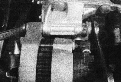
6.50 Loosen the upper alternator mounting nut - F3P engine models without power steering or air conditioning.
51. Loosen the adjusting nut to reduce tension, then remove the drive belt from the pulleys, noting its location.
Installation
52. Install the belt on the pulleys. Lightly tighten the adjusting nut. Make sure the belt is routed as noted before removal.
53. Tighten the drive belt as described in the following steps.
Tension
54. Proceed as described in points 46 - 50, if not already done.
55. Correct tension of the drive belt will ensure its long service life. However, do not overtighten it as this may cause excessive wear on the generator and/or water pump.
56. The belt should be tensioned so that when you press firmly with your thumb in the middle of the run between the crankshaft and generator pulleys, it deflects by approximately 2.5 - 3.5 mm (see illustration).
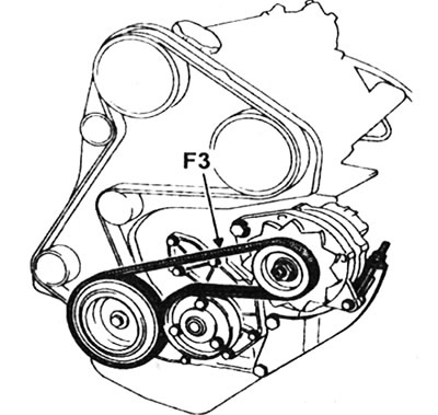
6.56 Auxiliary Drive Belt Tension Check Location (P3) - P3P Engine Models Without Power Steering or Air Conditioning. P3=2.5-3.5 mm (cold)/3.5-4.5 mm (warm).
57. Turn the adjusting nut until the correct tension is achieved, then tighten the lock nut and the generator mounting nut and bolts.
58. When a new belt is installed, it will stretch slightly when the engine is running. Let the engine run until the radiator fan comes on, then turn it off and check the belt tension again.
59. When the engine is warm, the belt should deflect by 3.5 - 4.5 mm, when using the method described in paragraph 56.
60. Finally, install the engine splash guard and wheel. Lower the car to the ground and install the headlight.
P3P engines - models with power steering and without air conditioning
Removal
61. Proceed as described in points 46 - 48.
62. Loosen the bolt in the center of the tensioner pulley using a 7mm Allen key.
63. Turn the tensioner pulley clockwise to decrease the belt tension.
64. Remove the belt from the pulleys.
Installation
65. Install the belt on the pulleys. Make sure it is routed correctly as noted before removal.
66. Tighten the drive belt as described in the following steps.
Tension
67. Proceed as described in points 61 - 62, if not already done.
68. Correct tension of the drive belt will ensure its long service life. However, do not overtighten it as this may cause excessive wear on the generator and/or pump.
69. The belt should be tensioned so that when you press firmly with your thumb in the middle of the run between the pulleys of the generator and the power steering pump, it deflects by approximately 3.5 - 4.5 mm (see illustration).
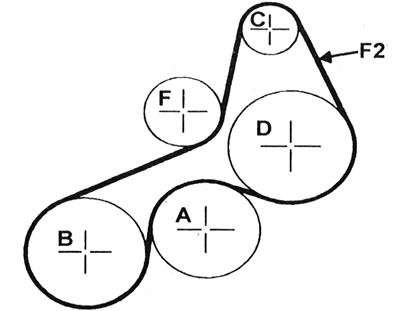
6.69 Auxiliary drive belt tension check location (P2) - P3P engine models with power steering and without air conditioning: A - Water pump pulley; B - Crankshaft pulley; C - Generator pulley; D - Power steering pump pulley; F - Tensioner pulley; P2 = 3.5 - 4.5 mm. amplifier (cold) / 5.5 - 7.0 mm (warm).
70. Turn the tensioner pulley clockwise until the correct tension is achieved. Lock the pulley and tighten the hex socket bolt.
71. Run the engine for approximately 5 minutes and check the belt tension again as described in paragraph 69.
72. When the engine is warm, the belt should deflect by 5.5 - 7.0 mm, when using the method, see paragraph 69.
73. Finally, install the engine splash guard and wheel. Lower the car to the ground and install the headlight.
P3P engines - models with air conditioning
Removal
74. Remove the right headlight as described in Section 12, Chapter 7.
75. Loosen the bolt in the center of the tensioner pulley using a 7mm Allen key (see illustration).
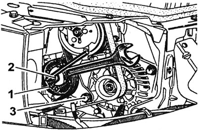
6.75 Loosen the auxiliary drive belt tensioner pulley bolt - RZR engine models with air conditioning: 1 - Tensioner pulley; 2 - Tensioner pulley bolt; 3 - Lower generator mounting bolt.
76. Turn the tensioner pulley clockwise to tighten the belt.
77. Remove the belt from the pulleys.
Installation
78. Install the belt on the pulleys. Make sure it is routed correctly as noted before removal.
79. Tighten the drive belt as described in the following steps.
Tension
80. Proceed as described in points 74 and 75, if not already done.
81. Correct tension of the drive belt will ensure its long service life. However, do not overtighten it as this may cause excessive wear on the generator and/or compressor.
82. The belt should be tensioned so that when you press firmly with your thumb in the middle of the run between the generator and compressor pulleys, it deflects by approximately 1.5 - 2.5 mm.
83. Turn the tensioner pulley clockwise until the correct tension is achieved. Lock the pulley and tighten the hex socket bolt.
84. Run the engine for approximately 5 minutes and check the belt tension again as described in step 82.
85. Install the headlight.
F7P engine (with 16 valves)
Removal
86. Remove the right headlight.
87. On models equipped with a charcoal canister, unscrew the two mounting bolts, remove the hose shield connecting the canister to the fuel tank, then disconnect the hose from the canister.
88. Loosen the screw securing the wiring bracket to the front fender inner panel. Rotate the bracket back to access the belt tensioner pulley bolt (see illustration).
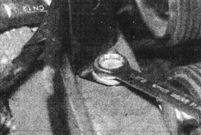
6.88 Loosen the screw securing the wiring bracket to the inner panel of the front wing - engine F7P (with 16 valves).
89. Loosen the bolt in the center of the tensioner pulley using a 7mm Allen key.
90. Turn the tensioner pulley clockwise to tighten the belt.
91. Apply the handbrake, then jack up the front of the car and place it on axle stands.
92. Remove the right front wheel, then loosen the mounting bracket and remove the engine mudguard from the subframe (see illustration).
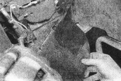
6.92 Remove the right mudguard - engine F7P (with 16 valves).
Please note that you must first separate the brake pad wear sensor wiring from the mudguard.
93. Working under the wheel arch, remove the two screws and the lower timing belt cover to gain access to the crankshaft pulley (see illustration).
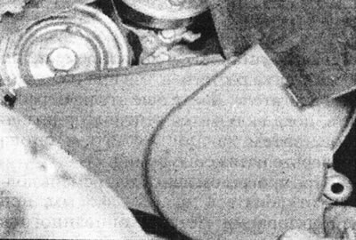
6.93 Remove the lower timing belt cover - F7P engine (with 16 valves).
94. Working through the headlight opening, carefully remove the drive belt from the pulleys (see illustration).
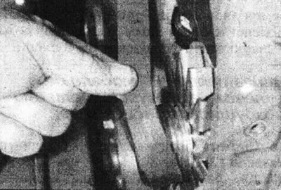
6.94 Remove the drive belt from the generator pulley - engine R7R (with 16 valves).
Installation
95. Install the belt on the pulleys. Make sure it is routed correctly as marked before removing.
96. Tighten the drive belt as described in the following steps.
Tension
97. Proceed as described in points 86 - 89, if not already done.
98. Correct tension of the drive belt will ensure its long service life. However, do not overtighten it as this may cause excessive wear on the generator and/or pump.
99. The belt should be tensioned so that when you press firmly with your thumb at the middle of the run between the power steering pump pulley or the idler pulley (where available) and the generator pulley deviated by approximately 1.5 - 2.5 mm (see illustration).
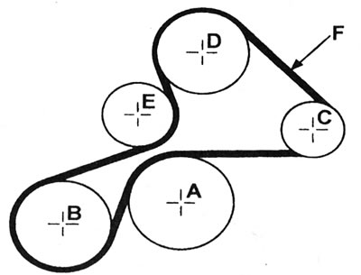
6.99 Drive belt tension check location (F) - F7P engine (with 16 valves): A - Water pump pulley; B - Crankshaft pulley; C - Generator pulley; D - Power steering pump pulley or idler pulley; E - Tensioner pulley; F = 1.5 - 2.5 mm.
100. Turn the tensioner pulley clockwise until the correct tension is achieved. Lock the pulley and tighten the hex socket bolt (see illustration).
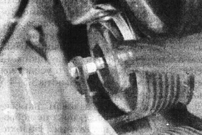
6.100 While holding the tensioner pulley, tighten the hexagon socket bolt - R7R engine (with 16 valves).
101. Tighten the screw securing the wiring harness bracket to the inner fender panel.
102. Run the engine for approximately 5 minutes and check the belt tension again as described in point 99.
103. Where available, connect the charcoal canister hose and install the shield.
104. Install the headlight.
D-Series Engine - Alternator Drive Belt
Removal
105. Remove the power steering pump drive belt.
10b. Loosen the generator mounting bolts, move the generator and remove the belt from the pulleys (see illustration).
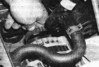
6.106 Remove the alternator drive belt - D-series engine.
Installation
107. Install the belt on the pulleys. Move the generator away from the engine and lightly tighten the nuts and bolts.
108. Tighten the drive belt as described in the following steps.
Tension
109. The belt should be tensioned so that when firmly pressed with the thumb at the middle of the run between the pulleys, it deflects approximately 4.0 mm.
110. Pull the alternator away from the engine until the correct tension is achieved, then tighten the mounting bolts.
111. Finally, install the power steering pump drive belt.
D-Series Engine - Power Steering Pump Drive Belt
Removal
112. Working in the engine compartment, use a suitable Allen key to loosen the center bolt while holding the belt tensioner pulley with the key (see illustration).
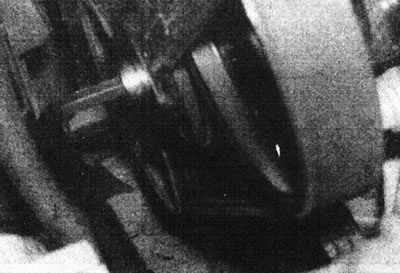
6.112 While holding the pulley with a wrench, loosen the pulley center bolt with a socket wrench-D-series engine.
113. Remove the drive belt from the pulleys (see illustration).
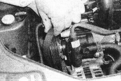
6.113 Remove the power steering pump drive belt - D-series engine.
Installation
114. Install the belt on the pulleys. Remove slack by turning the tensioner pulley with a wrench, then lightly tighten the center bolt.
115. Tighten the drive belt as described in the following steps.
Tension
116. The belt should be tensioned so that when you press firmly with your thumb at the middle of the run between the pulleys of the power steering pump and the crankshaft, it deflects by approximately 3.0 mm (see illustration).
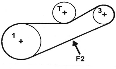
6.116 Check location for tension of power steering pump drive belt (P2) - D-series engine: 1 - Crankshaft pulley; 3 - Power steering pump pulley; T - Tensioner pulley.
117. Turn the tensioner pulley until the correct belt tension is achieved. Then, while holding the tensioner pulley with a wrench, tighten the center bolt.