
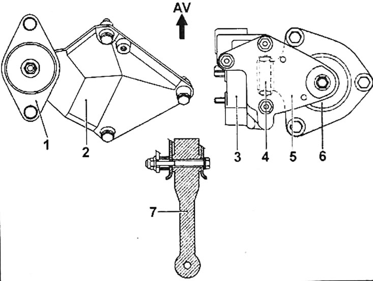
Pic. 1.62. Pendulum engine mount. 1 - elastic cushion of the front left pendulum suspension; 2 - pendulum suspension bracket on the gearbox; 3 - pendulum suspension bracket on the cylinder head; 4 - travel limiter of the pendulum suspension; 5 - cover of the pendulum suspension; 6 - elastic cushion of the front right pendulum suspension; 7 - jet thrust
The engine is suspended on two elastic cushions (1 and 6. fig. 1.62). The perception of moment in the longitudinal direction is carried out:
- in the lower part of the power unit with jet thrust (7);
- in the upper part of the power unit with a travel limiter (4).
Note. To avoid damage to the elastic cushions, do not exceed 20°angular movement relative to the vertical.
Adjusting the longitudinal stroke limiter
- Use a support to support the power unit.
- Loosen the pendulum suspension travel limiter bolts (4).
- Insert centering fork Mot. 1289-02 in the slot of the pendulum suspension cover (5).
Note. This operation can only be carried out with the bracket and cushion installed on the gearbox and their mounting bolts tightened to the required torque. Then tighten the torque rod.