
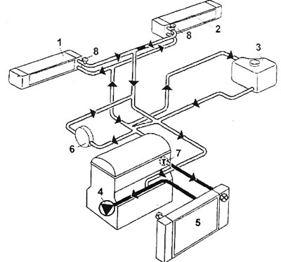
Pic. 1.86. F3R engine cooling system diagram: 1 - right interior heating radiator; 2 - left interior heating radiator; 3 - expansion tank; 4 - water pump; 5 - engine radiator; 6 - throttle body heating system; 7 - engine output hose and thermostat; 8 - air removal plugs
- Apart from replacing the coolant at prescribed intervals, maintenance is limited to checking the coolant level in the expansion tank.
- Remove the plug from the expansion tank
- Place a suitable container under the lower radiator reservoir hose connection.
- Disconnect the hose from the lower radiator reservoir and drain the coolant.
- Unscrew the air bleed plugs on the radiator and the supply hoses to the radiators of the heating system (pic. 1.88).
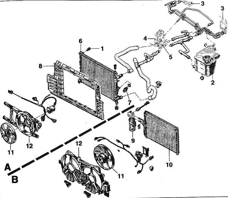
Pic. 1.87. Engine cooling system components: A - without air conditioning system; B - with air conditioning system; 1 - air bleed plug on the radiator; 2 - expansion tank; 3 - interior heating radiator; 4 - cylinder head; 5 - thermostat housing; 6 - radiator; 7 - temperature sensor; 8 - pipe; 9 - refrigerant tank; 10 - condenser; 11 - electric driven fan; 12 - fan casing with electric drive
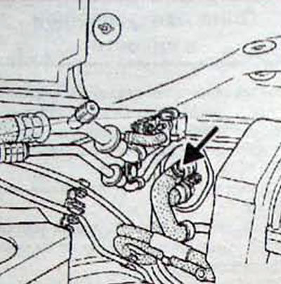
Pic. 1.88. Location of the air bleeder plug