
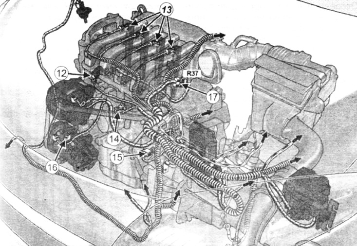
K4M engine
Disconnect connectors:
- block of wires from the air temperature sensor (12);
- wiring harnesses for ignition coils (13);
- knock sensor (14);
- oil pressure sensor (15);
- air conditioning compressor (16);
- engine/injection harness connections (17).
Disconnect the wiring harness from the intake manifold.
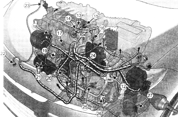
M4R engine
Disconnect connectors:
- R67 Circuits between vehicle front wiring harness and engine wiring harness (12);
- R20 circuit between engine harness and ignition harness (13);
- R24 circuit between engine harness and injection harness (14);
- camshaft position sensor (15);
- coolant temperature sensor (16);
- knock sensor (17);
- air temperature sensor (18);
- oil pressure sensor (19);
- oil level sensor (20);
- air conditioner compressor (21);
- pressure sensor in the cooling system (22);
- adsorber purge solenoid valve (23);
- multifunction switch (24);
- gearbox input shaft speed sensor (25);
- automatic transmission valve (26);
- ECU automatic transmission (27).
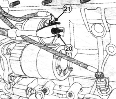
Remove:
- starter cable nut (20);
- fastening nut (21) starter excitation wires.
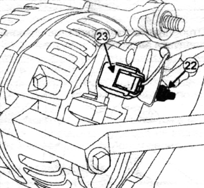
Loosen the nut (22) generator power wires.
Disconnect the wiring harness (23) from the generator.
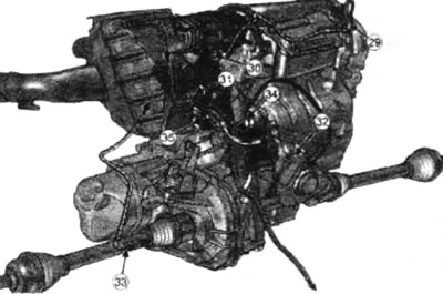
Disconnect connectors:
- pressure sensor (29);
- throttle body (30);
- sensor (31) coolant temperature;
- wiring harness from oil level sensor (32);
- light switch (33) reversing;
- upstream oxygen sensor (34);
- engine crankshaft position sensor (35).
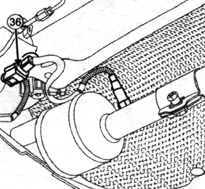
Disconnect connector (36) downstream oxygen sensor.
Disconnect:
- downstream oxygen sensor wiring from heat shield;
- manual transmission wiring.
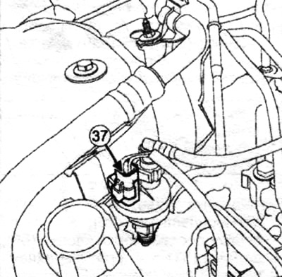
Disconnect the canister purge valve connector (37).
 |  |
Disconnect the body canister purge valve harness.
Disconnect connector (38) refrigerant pressure sensor.
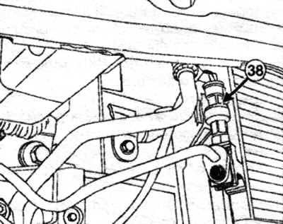
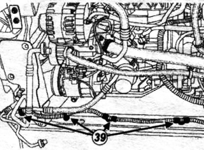
Disconnect the refrigerant pressure sensor harness and canister purge valve harness from the radiator support cross member at (39).
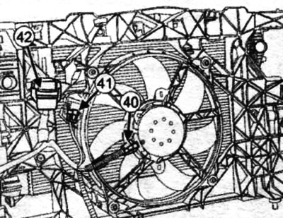
Disconnect:
- wiring block (40) from an electric fan;
- resistor connector (41).
Disconnect the relay box (42) from the front body panel.
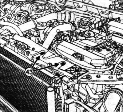
Loosen the mounting bolts (43) engine wiring harness troughs.
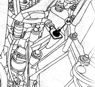
Note. Before removal «mass» terminal, mark its position with an indelible pencil by drawing a line from «ground terminal» to the gearbox housing.
Wrong position when assembling «mass» terminals on the gearbox housing can damage «mass» terminals or «mass» wiring.
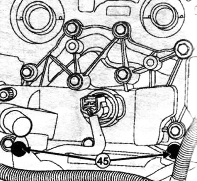
Remove the bolt (44) wire end fasteners «masses».
Take aside «mass» the wire.
Loosen the mounting bolts (45) engine wiring harness troughs. Set aside the engine wiring harness groove.
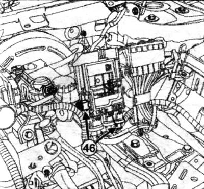
Disconnect connectors (46) battery disconnect unit. Disconnect the battery disconnect harness.
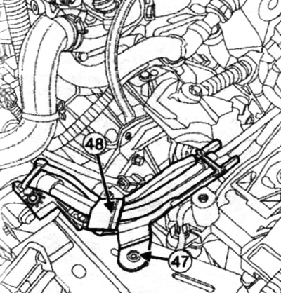
Drill out the rivet (47) power wiring harness troughs.
Disconnect the power harness groove (48).
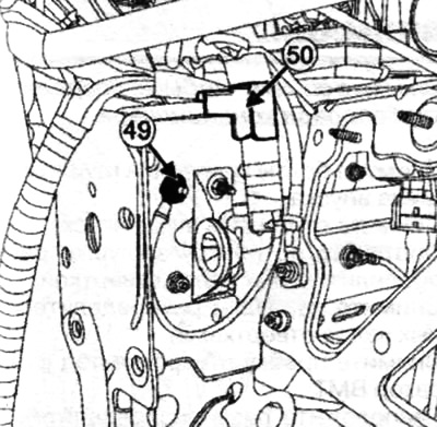
Remove:
- «mass» tire (49) on the left front side member;
- tip «mass» wire on the left front side member.
 |  |
Disconnect «mass» wire at point (50).
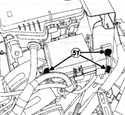
Remove fasteners (51) from the fuse box in the engine compartment. Set aside the fuse box in the engine compartment.
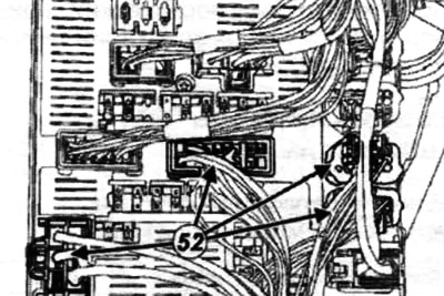
Disconnect connectors (52) block of protection and switching.
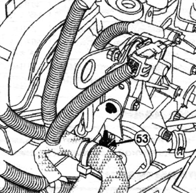
Set aside the wiring harness. Loosen the fastening nut (53) engine wiring on the lifting eye.
 |  |
Attention. To prevent damage during installation, make sure the wiring harness is not secured (holder, plastic tie, adhesive tape, non-disconnected connector, etc.).
Remove the engine wiring harness.
When replacing with a more complete wiring harness, fix unused connectors.
Attention. In order not to damage the wiring harness during installation, respect its original gasket.
Correctly position the wire holder on the engine wire bracket.
Install the engine wiring nut on the lifting lug.
Install the engine wire harness groove.
Install the engine wiring harness groove bolts.
Connect the connectors to the protection and switching unit.
Install the fuse box in the engine compartment.
Install the fuse box mounts in the engine compartment. Fasten «mass» the wire.
Install:
- tip «mass» wires on the left front side member,
- fastening nut «mass» wires on the left front side member.
Torque tighten the fastening nut «mass» wires on the left front side member 8 Nm.
Attach the power wire harness groove.
Install a new rivet on the power wire harness groove.
Attach the wiring harness to the battery disconnect box. Connect the battery disconnect connectors. Install harness «massive» wires.
Install the tip bolt «mass» wires on the crankcase of a manual transmission.
Note.
- Set tip «mass» wires on the mark made with an indelible pencil on the tip «mass» wires and to the gearbox housing.
- Wrong position when assembling «mass» terminals on the gearbox housing may damage it or «mass» wiring.
Torque tighten the handpiece mounting bolt «mass» wires on the crankcase of a manual transmission 24 Nm.
Install the engine harness groove mounting bolts on the front body panel.
Attach the relay box to the front panel of the body.
Attach the wiring harness from the electric fan and the resistor connector.
Attach the refrigerant pressure sensor harness and canister purge harness to the radiator support cross member.
Connect the refrigerant pressure sensor connector.
Attach the canister purge harness to the body.
Connect the canister purge connector.
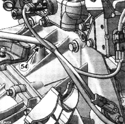
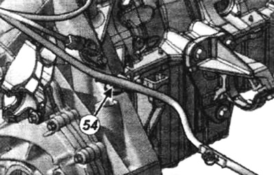
Attach the wiring harness to the manual transmission at the point (54).
 |  |
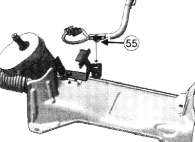
Attach the downstream oxygen sensor harness to the heat shield and to the point (55).
Connect all connectors.
Install the alternator power cable nut and tighten to 21 Nm.
Install:
- starter power wire fastening nut;
- starter excitation cable nut.
Torque tighten:
- nut for fastening the starter power wire 8 Nm;
- nut of fastening of a wire of a chain of excitation of a starter 5 Nm.
Connect the wiring to the intake manifold:
Attach the Protection and Switching Unit.
Install the protection and switching unit cover.
Turn on the ignition.
Connect the diagnostic tool and check that there are no faults.