- electrical appliances with assigned number,
- connectors marked with a letter followed by a number (R107),
- connections with "weight", denoted by a letter followed by a letter or number (e.g. M4 or MG).
Schematic diagrams are supplemented:
- indicating the purpose of the wires in each connector,
- wiring diagrams that allow you to determine the location of elements on the car,
- lists of functions, devices, connectors, connections to "weight", chains.
Wire colors
The main electrical circuits use wires of the following colors:
| Red | "+" 12 V before ignition switch |
| Yellow | "+" 12 V after ignition switch |
| Blue | chain of position lights or direction indicators |
| Black | direct connection to "mass" |
The remaining wires and connectors are painted in the following colors: White, Blue, Beige, Transparent, Grey, Yellow, Brown, Black, Orange, Red, Pink, Green, Violet.
| VA | White |
| BE | Blue |
| BJ | Beige |
| CY | Transparent or white |
| GR | Grey |
| JA | Yellow |
| MA | Brown |
| NO | Black |
| OR | Orange |
| RG | Red |
| SA | Pink |
| VE | Green |
| VI | Violet |
chains "+" starter, interleaved connections with "weight", polarity reversal circuits do not belong to the main electrical circuits.
Presence or absence of circuit protection devices (fuses and bimetal fuses) does not affect the applicability of electrical wires.
The colors of electrical wires on electrical equipment supplied as spare parts do not comply with the above rules in all cases.
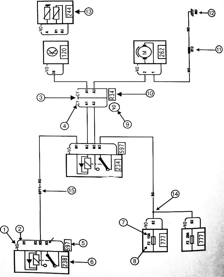
Schematic reading example:
| 1 | Connector color. |
| 2 | Connector diagram. |
| 3 | Connection diagram. |
| 4 | Connector color. |
| 5 | Board number to which the device is connected. |
| 6 | Device number. |
| 7 | Rated fuse current. |
| 8 | Location of the fuse on the board. |
| 9 | Holder color. — |
| 10 | Connection number. |
| 11 | Wire splice number. |
| 12 | Connection number from "weight" |
| 13 | Auxiliary element. |
| 14 | Connection diagram. |
| 15 | Circuit code (allows you to determine the purpose of the wire), see circuit list. |
Note: Auxiliary element: in the diagram shown, this element transmits information to the computer on the basis of which the relay is controlled. In more detail, the connections between the elements and the ECU are presented in the corresponding diagram.