



The liners are installed using a tool (Mot. 1492).
Select the liner holder according to the engine model (the engine model is indicated on the bracket).
Install the liner holder into the support groove.
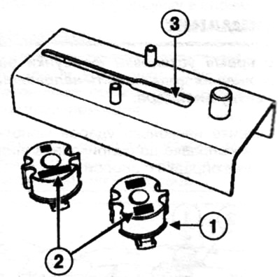
Installing the insert holder into the support groove:
1 - insert holder;
2 - engine model marking;
3 — support groove.
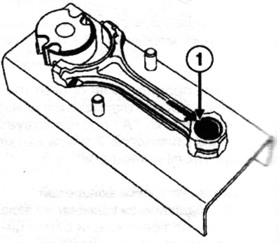
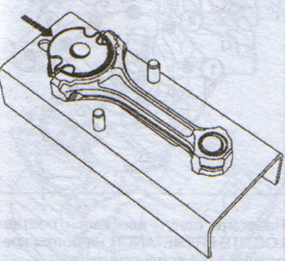
Install the connecting rod on a special device.
Press the lower part of the connecting rod upper head (1) against the centering pin.
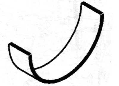
Install the bearing shell (1) onto the support. Push the bearing shell support in the direction shown by the arrow in the figure until it goes all the way into the connecting rod crank head.
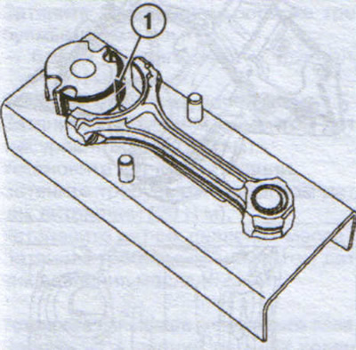 |
 |
Remove the bearing support (1) from the connecting rod crank head and repeat the operations with the remaining connecting rods.
Place the connecting rod cover against the protrusions on the support (2).
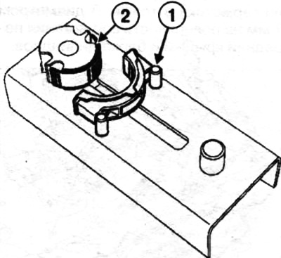
Install the connecting rod bearing onto the bearing support.
Push the bearing retainer in the direction shown by the arrow in the illustration until the bearing retainer fits into the connecting rod cap as far as it will go.
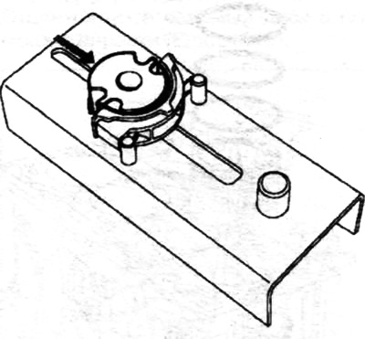
Remove the bearing support from the connecting rod cap and repeat the operations with the remaining connecting rod caps.