
Note:
Necessary equipment:
- 1. Safety (e) belt (neither);
- 2. Hydraulic jack;
- 3. Indelible pencil;
- 4. Torque wrench;
- 5. Diagnostic tool.
Attention: When performing the operation, wear tight waterproof protective gloves (e.g. nitrile).
Removing
1. Place the vehicle on a two post lift.
2. Remove the engine undertray.
3. Drain the oil from the engine.
4. Remove the oil filter.
5. Remove the lower jet rod.
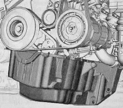
6. Fix the radiator on the car with a belt using a safety (e) belt (neither).
7. Remove the front suspension subframe.
8. To remove the basic bearing of a shaft of a drive of the right forward wheel.
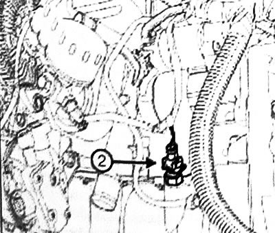
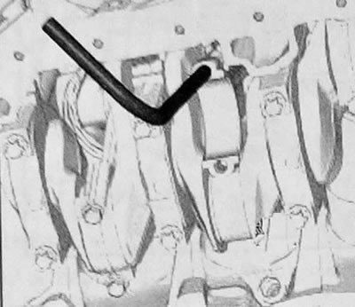
9. Disconnect the oil level sensor connector (if installed) (2).
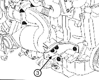
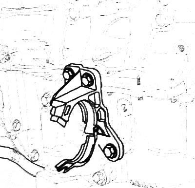
10. Remove the top brace (3) catalytic converter.
Attention: Failure to follow the instructions for the following operation may result in damage to the oil receiver of the oil pump.
11. To turn away bolts of fastening of the pallet crankcase of the engine.
12. Install «Hydraulic jack» for engine oil pan support.
13. Remove the engine sump bolts.
14. Remove the engine oil pan, holding it with «hydraulic jack».
15. Tilt the engine sump forward to access the oil pump mounting bolts.
16. Partially loosen the engine sump bolts by 3 - 5 mm.
17. Disconnect the oil pump to remove the engine oil pan.
18. Remove:
- engine oil pan,
- engine oil pan gasket,
- oil pump.
Removing the connecting rod bearing shells of cylinder No. 2
19. Clear «SURFACE CLEANER» lower connecting rod heads.
20. Mark the position of the connecting rod cap relative to the connecting rod with an indelible pencil.
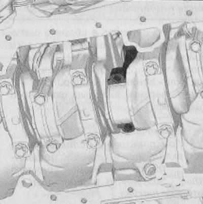
21. Set the crankshaft to TDC.
22. Remove:
- connecting rod bolts,
- rod cover,
- lower connecting rod bearing.
Note: When reusing conrod bearing shells, mark the position of the lower conrod bearing shell relative to the con rod cap.
23.Clear «SURFACE CLEANER» mating surfaces of connecting rod caps.
24.Install the connecting rod of the tool (Mot. 1914) on the connecting rod.
25. Move the connecting rod up to release it from the connecting rod journals.
26. Rotate the crankshaft 90" clockwise (from the timing drive).
Caution: Failure to follow this procedure may result in damage to the piston cooling nozzles.
27. Pull the piston and connecting rod assembly using the connecting rod of the tool (Mot. 1914), being careful not to let the piston touch the piston head cooling jets.
28. Remove the upper shell of the connecting rod bearing.
Note: When reusing connecting rod bearing shells. Mark the position of the upper connecting rod bearing relative to the connecting rod.
29. Clear «SURFACE CLEANER» mating surfaces of bearings on the connecting rod housing.
Installation
Installing the connecting rod bearing shells for cylinder No. 2
1. Parts subject to mandatory replacement:
- Connecting rod cap bolts (10,03,02,10).
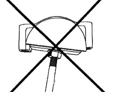
Note: Be sure to replace the 20mm wide conrod bearing shells with the 18mm wide conrod bearing shells. If the set of conrod bearing shells consists only of 18 mm wide conrod bearing shells, use only the tool head (Mot. 1920) labeled "K9K SUP".
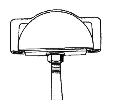
2. Install fixture head (Mot. 1920) labeled " K9K INF " on the threaded socket of the device (Mot. 1914).
3. Install the connecting rod bearing lower shell onto the tool (Mot. 1920).
Note: The mating surfaces of the bearing shell and connecting rod must be dry and free from grease.
4. Install the lower connecting rod bearing shell to the connecting rod cap using a tool (Mot. 1920).
5. Install the lower shell of the connecting rod bearing so that the edges do not protrude beyond the connecting rod cover.
6. Lubricate the surface of the connecting rod bearing (from the cheeks of the crankshaft) fresh engine oil.
7. Remove the head with a mark "K9K INF" and install the head marked "K9K SUP".
8. Install the connecting rod bearing upper shell onto the tool (Mot. 1920).
9. Install the upper connecting rod bearing shell on the connecting rod using a tool (Mot. 1920).
10. Install the upper shell of the connecting rod bearing so that the edges do not protrude beyond the connecting rod housing.
11. Lubricate the surface of the connecting rod bearing (from the side of the crankshaft) fresh muscle oil.
12. Move the piston assembly r, step, nom into place.
13. Turn the crankshaft % counterclockwise.
14. Lubricate the connecting rod journal with fresh engine oil.
15. Pull the piston and connecting rod assembly to install the connecting rod on the crankshaft.
Note: Before installing the connecting rod cap, make sure that there is no dirt (shavings, fleecy residues of rags, etc.) on the surfaces of the connecting rod or cap.
16. Install:
- connecting rod cap in accordance with the mark made during removal,
- new connecting rod bolts.
17. Tighten to the required torque and tighten the connecting rod cap bolts to the specified angle (20 Nm +45°±6°).
Removal - installation of liners of connecting rod bearings of cylinders No. 3, 1 and 4.
18. Perform the same operations for removing the connecting rod bearing shells of the cylinders as on cylinder No. 2.
Note: To remove and install the connecting rod bearing shells for cylinders No. 1 and 4, install the pistons at BDC before performing the same removal and installation operations for the connecting rod bearing shells as for cylinder No. 2.
19. Parts subject to mandatory replacement:
- A) Engine oil pan gasket (10,03, 01,09);
- b) Oil filter (10,05,05,03);
- V) Engine oil pan drain plug gasket (10,03,01,04).
Attention:
- 1. Do not scrape the mating surfaces of the aluminum parts, as any damage to the mating surface may subsequently lead to fuel leaks.
- 2. To ensure sealing, mating surfaces must be clean, dry and free of oil (don't touch them with your fingers).
20. Using a wooden spatula or MATTING WHEELS, clean the mating surfaces of the cylinder block and the engine oil pan.
21. Install the oil pump
22. Screw in, without tightening the oil pump mounting bolts, maintaining a gap of 3 mm - 5 mm.
23. Install the engine pan gasket.
Caution: Applying too much sealant can cause sealant to be squeezed out when parts are tightened. The ingress of sealant into the coolant can cause damage to some components and assemblies (radiator motor, etc.).
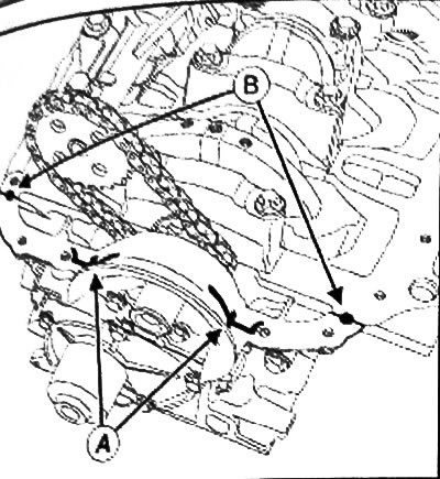
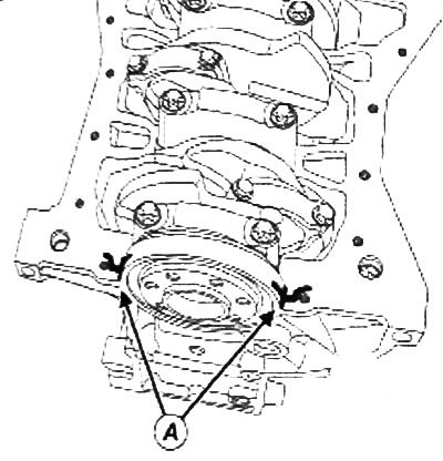
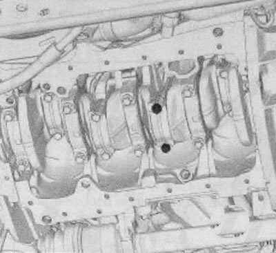
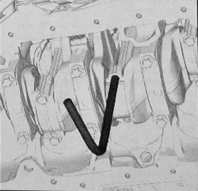
24. Apply «SILICONE GASKET»:
- four beads with a diameter of 5 mm at a point (A),
- two drops with a diameter of 5 mm at a point (IN).
25. Reinstall the engine oil pan while holding it with help «hydraulic jack».
26. Tilt the engine sump forward to access the oil pump mounting bolts.
27. Torque tighten the oil pump mounting bolts (25 Nm) with help «torque wrench» PROS-TEEL part number 77 AND 226 888 from 13 mm bolt.
Note: Make sure that the engine oil pan gasket is actually in place before tightening the engine oil pan bolts.
28. Install the engine sump bolts.
29. Torque tighten the engine sump bolts in the order shown.
30. Install the upper strut of the catalytic converter.
31. Connect the oil level sensor connector.
32. Install the support bearing on the right front wheel drive shaft.
33. Install the front suspension subframe.
34. Remove the safety (e) belt (neither) from the radiator.
35. Install the lower jet thrust.
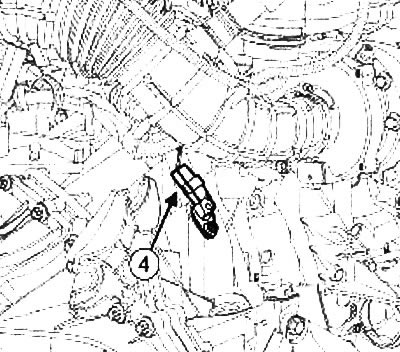
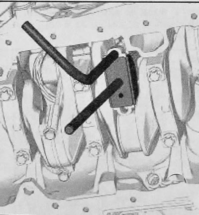
36. Disconnect the crankshaft position sensor connector (4), to prevent the engine from starting.
37. Install the oil filter.
38. Fill the engine with oil.
39. Start the engine and wait until the oil pressure warning light goes out.
40. Connect the wiring harness to the crankshaft position sensor.
41. Install the engine undertray.
42. Clear stored faults using the diagnostic tool.