
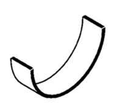
Pic. 2.168. Insert without mustache
The engine is equipped with liners without a mustache (pic. 2.168).
Inserts are installed with a tool (Mot. 1492).
Select the liner holder according to the engine model (engine model is indicated on the bracket).
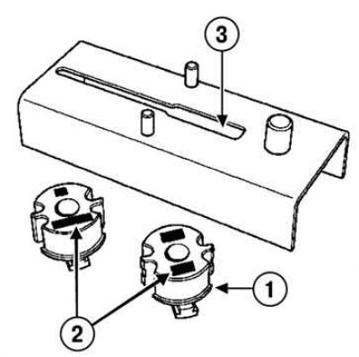
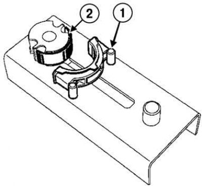
Pic. 2.169. Installing the insert holder in the support groove: 1 - insert holder; 2 - marking of the engine model; 3 - support groove
Install the liner holder in the support groove (pic. 2.169).
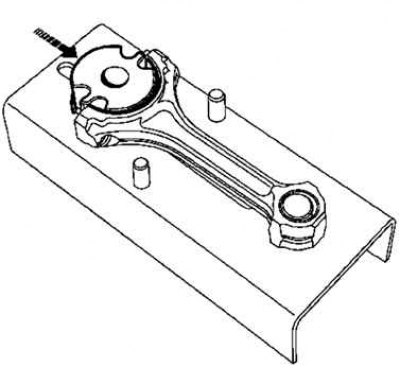
Install the connecting rod on the special tool.
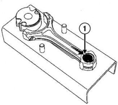
Pic. 2.170. Installing the connecting rod on a special tool: 1 - the lower part of the upper head of the connecting rod
Press the bottom of the upper end of the connecting rod against the alignment pin (pic. 2.170).
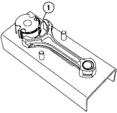
Pic. 2.171. Installing the liner on the support: 1 - insert
Install the liner on the support (pic. 2.171).
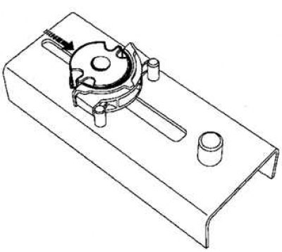
Pic. 2.172. Direction of movement of the bearing support
Push the support of the loose leaf in the direction shown in Figure 2.172 by the arrow, it will not go all the way into the crank head of the connecting rod.
Remove the bushing support from the connecting rod crank head and repeat the operations with the rest of the connecting rods.
Pic. 2.173. An emphasis of a cover of a rod in protrusions on a support: 1 - insert; 2 - support
Push the connecting rod cap into the tabs on the support (pic. 2.173).
Pic. 2.174. Installing the connecting rod bearing on the support
Install the connecting rod bushing on the bushing support (pic. 2.174).
Push the insert holder in the direction shown by the arrow in Figure 2.174 until the insert holder comes all the way into the connecting rod cover.
Remove the bushing support from the connecting rod cap and repeat the operations for the rest of the connecting rod caps.