
English Русский
Български
Беларускі
Український
Српски
Hrvatski
Română
Polski
Slovenský
Magyar
Bookmark Contacts Articles Sitemap
Company vehicles Peugeot Company vehicles Opel Company vehicles Skoda Company vehicles Land Rover Company vehicles Mitsubishi Company vehicles Volkswagen Company vehicles Honda
RenaultBook.ru


Duster   Fluence   Kangoo   Laguna   Logan   Megane   Sandero   Scenic   Symbol   Clio   Other
Clio 1 (1990-1998)

Piston/Connecting Rod Assemblies — checking connecting rod bearing clearance and installation (Renault Clio 1)

  • Main
  • Clio
  • Clio 1 (1990-1998)
  • Power unit
  • Overhaul of engines
  • Piston/Connecting Rod Assemblies — checking connecting rod bearing clearance and installation
0
Contents: C- and E-series engines 🠛 D- and F-series engines 🠛
1. Clean the backs of the bearing shells and the bearing surfaces in the connecting rods and caps. If new bearings are being installed, remove the protective grease from them using kerosene. Wipe the liners with a dry, thick (lint-free) cloth.

2. Insert the liners into their places in the connecting rods and caps. Make sure the mounting tabs fit into the slots in the cranks (see illustration).
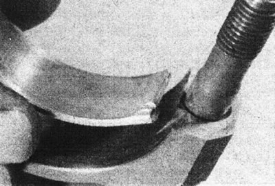
20.2. The tongue on the bearing shell must fit into the recess in the connecting rod.

20.2. The tongue on the bearing shell must fit into the recess in the connecting rod.


C- and E-series engines


Checking the connecting rod bearing operating clearance


3. Lay out the four sleeves in the order they will be installed, with the working surface facing down. Install pre-selected seals into the base of each cylinder liner (see illustration).
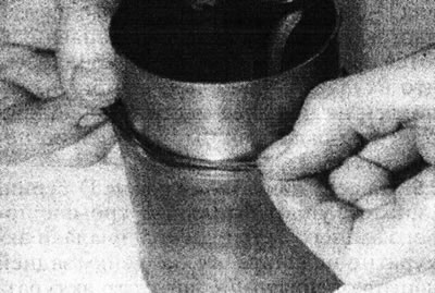
20.3. Install the lower cylinder liner O-ring (e-series engine).

20.3. Install the lower cylinder liner O-ring (e-series engine).


4. Lubricate the pistons and piston rings, then place each piston/connecting rod assembly next to its corresponding liner.

5. Begin assembly with piston #1, first checking that the piston ring cuts are evenly spaced (120° apart). Compress the piston rings with a special tool.

6. Insert the piston/connecting rod assembly into the base of the cylinder bore. Make sure the arrow on the piston head points towards the flywheel/drive plate. Using a block or hammer handle, drive the piston into the sleeve until the piston head is approximately 25 mm from the top of the sleeve.
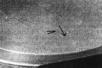
20.6. The arrow on the piston head must point towards the flywheel.

20.6. The arrow on the piston head must point towards the flywheel.


7. Repeat the procedure with the remaining three piston and liner assemblies.

8. Turn the crankshaft so that connecting rod journal No. 1 is at bottom dead center.

9. With the liner O-ring in place, place the liner with the piston/connecting rod assembly into the cylinder block. The arrow on the piston head must point towards the flywheel/drive plate.

10. To measure the connecting rod bearing operating clearance, see. information in Chapter 19.

11. After installing the sleeve/piston assembly, secure the sleeve with a bolt and washer, or a clamp (see illustration).
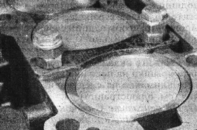


20.11. Fixing cylinder liners using clamps.

20.11. Fixing cylinder liners using clamps.


12. Repeat the above procedures with the remaining assemblies.

Original of this article on the website: renaultbook.ru

Final installation


13. After checking the running clearance of all crankpins, wash off all traces of Plastigauge from the bearings and crankpins.

14. Generously lubricate the crankshaft journals and connecting rod bearings. Install the bearing caps. Tighten the cover nuts/bolts to the specified tightening torque Specifications, check how the crankshaft turns every time. Finally, make sure that all the sleeves are correctly positioned relative to each other (a 0.1 mm thick feeler gauge should be able to pass freely through the gaps between them) (see illustration).
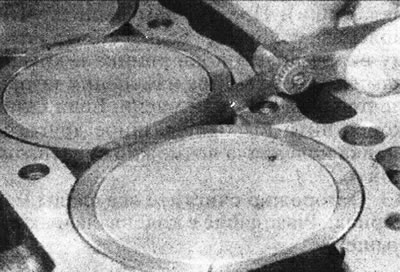
20.14. Check the gap between the sleeves.

20.14. Check the gap between the sleeves.


If this is not the case, it may be necessary to swap one or more piston/liner assemblies to achieve this clearance.

D- and F-series engines


Checking the connecting rod bearing operating clearance


15. Lubricate piston No. 1 and rings, making sure that the ring cuts are evenly spaced from each other (120°).

16. Install the compressor onto piston #1, then insert the piston and connecting rod into cylinder #1. With the crankshaft journal at bottom dead center, carefully insert the piston into the cylinder while simultaneously guiding the connecting rod onto the crankshaft journal (see illustration).
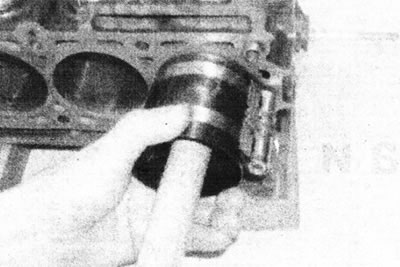
20.16 Using a wooden hammer handle, carefully tap the piston into the cylinder - D-series engine…

20.16 Using a wooden hammer handle, carefully tap the piston into the cylinder - D-series engine shown.


Make sure the arrow on the piston head surfaces points towards the flywheel.

17. To measure the connecting rod bearing operating clearance, see. information in Chapter 19.

18. Repeat the above procedures with the remaining piston/connecting rod assemblies.

Final installation


19. After checking the running clearance of all crankpins, wash off all traces of Plastigauge from the bearings and crankpins.

20. Generously lubricate the journals and shells of the connecting rod bearings. Install the bearing caps. Tighten the mounting bolts to the specified tightening torque Specifications, each time checking that the crankshaft turns freely.
This article is available on: russian, bulgarian, belarusian, ukrainian, serbian, croatian, romanian, polish, slovak, hungarian
Article has been reviewed by editor: Fedoseev Denis
Share with friends:
Previous
Clio 1: Overhaul of engines
Next

Crankshaft — checking the main bearing clearance and installation
Engine overhaul — assembly sequence
Main and connecting rod bearings — inspection
Crankshaft — inspection
Piston/Connecting Rod Assemblies — inspection and assembly
Engine — starting after overhaul
Other articles on other Renault models

➽ Checking the connecting rod bearing clearance and installing the… Renault Megane 1 (1995-2002)
➽ Clearance between piston pin and connecting rod upper head of… Renault Fluence 1 (2009-2020, petrol)
➽ Connecting rod bearing shell Renault Duster 1 (2009-2017)
➽ Replacing connecting rod bearing shells Renault Logan 2 (2012-2020)
➽ Removal, disassembly and assembly of the connecting rod and… Renault Symbol 1 (1999-2008, petrol)
Link to this article in different formats
Reviews and comments of visitors
No comments yet


Add two numbers 30 + 46


Clio 1 (1990-1998) 
  • General information
  • Maintenance
  • Troubleshooting
  • Power unit
  • Petrol engines 1.1 l (C)
  • Petrol engines 1.2 l (D)
  • Petrol engines 1.2/1.4 l (E)
  • Petrol engines 1.8 l (F)
  • Diesel engines
  • Overhaul of engines
  • Cooling and heating
  • Fuel system (carburetor)
  • Central fuel injection
  • Distributed fuel injection
  • Fuel system (diesel)
  • Starting and charging system
  • Ignition system (transistor)
  • Ignition system (electronic)
  • Pre-heating of diesel engines
  • Transmission
  • Clutch
  • Manual gearbox
  • Automatic gearbox
  • Drive shafts
  • Chassis, running gear
  • Brake system
  • Car suspension
  • Steering system
  • Body and interior
  • Exterior (external elements)
  • Doors, locks and windows
  • Electrical equipment
  • Equipment and devices
  • Electrical circuits
RenaultBook.ru © 2018–2026 | Mobile version | News and articles | Sitemap: EN BG BY UA RS HR RO PL SK HU | Administration | Site search | Bookmark
Duster 1 (2009-2017) | Fluence 1 (2009-2020, petrol) | Kangoo 1 (1997-2007) | Laguna 2 (2001-2007) | Logan 1 (2004-2012, petrol) | Logan 2 (2012-2020) | Megane 1 (1995-2002) | Megan 2 (2002-2009, petrol) | Sandero 1 (2007-2012, petrol) | Scenic 1 (1996-2003) | Symbol 1 (1999-2008, petrol) | Symbol 2 (2008-2013, petrol) | Renault 19 (1988-1996) | Espace I and II (1984-1996) | Espace III (1996-2002) | Clio 1 (1990-1998) |
We want your visit to be comfortable 😌 and use cookies 🍪 to do so.