
Generator check
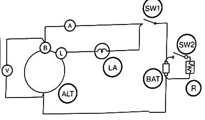
Perform a test of the generator on the stand according to the scheme given above, using:
- ammeter with scale 0-150 A (for 110 A generator) or ammeter with a scale of 0 - 100 A (for 70 A generator),
- voltmeter with a scale of 0-30 V,
- resistor with variable resistance, more than 150 A (for 110 A generator) or resistor with variable resistance, more than 100 A (for 70 A generator).
1. Checking the regulated voltage
1. Close contact (SW1) , while the contact (SW2) should be open.
In this case, the indicator lamp (LA) should be lit: if it is not lit, measure the voltage at terminal L.
2. Check if the voltage value on the generator is close (ALT) (terminal L, pin 1) to the battery voltage.
Low voltage indicates that the test lamp or its wiring is faulty.
3. Gradually increase the alternator speed, observing how the control lamp lights up at a speed of 2000 rpm.
A voltage above 15V indicates a regulator failure. If the applied voltage does not exceed the battery voltage, the alternator will not produce current.
In this case, the generator should be removed to identify the faulty component.
4. Gradually increase the generator speed to 5000 rpm.
If the ammeter reading does not exceed 5 A, measure the voltage: this is a regulated voltage.
Since the regulator is a temperature compensation element, the regulated voltage varies depending on the temperature of the regulator. If the temperature exceeds 10°C, the regulated voltage is reduced by approximately 0-0.12 V.
5. If the alternator current exceeds 5 A, continue charging until it drops below 5 A or replace the battery (BAT) charged.
Replace voltage regulator if regulated voltage is not 14.4±0.3V (at 20°C).
2. Current test
1. Close contact (SW1): The indicator lamp must be on.
2.Increase load resistance (R) up to the maximum value (decrease the current value).
3. Close contact (SW2). Set the generator speed to 3000 rpm.
4. Adjust the load resistance so that the voltage at terminal B is 13.5 V.
5. After 30 minutes, adjust the load resistance to provide a voltage of 13.5 V at terminal B.
6. Increase the speed to 6000 rpm.
7. Check the ammeter readings:
- the value must be at least 72.5 A for a 70 A generator and at least 108 A for a 110 A generator (measurements are carried out in a heated state). If the specified values are not correct, remove the alternator to isolate the faulty component.
Rotor replacement
1. Mark the installation position of the front and rear bearings.
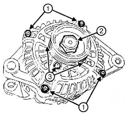
2. Loosen the screws (1) front bearing.
Note: To avoid damage to the stator winding, do not insert the screwdriver further than 2mm.
3. Disconnect the front bearing pulley and rotor assembly from the stator and rear bearing assembly using a flathead screwdriver.
Note: Be careful not to damage the rotor poles when removing the pulley nut.
4. Install the pulley in a vise, laying the old belt between the jaws so as not to damage the pulley.
5. Remove:
- pulley nut (2),
- bypass roller,
- front bearing.
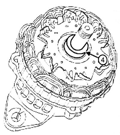
6. Remove spacer (4).
Note: If the front bearing is noisy or jerky when running, it is recommended to check the condition of the bearing when it is installed in the housing.
7. Check the condition of the front bearing for:
- extraneous noise,
- lubricant leaks (if the leak is small, wipe and remove traces of grease),
- uneven rotation.
8. Remove:
- four bolts (3) bearing limiter,
- bearing limiter.
9. Remove the bearing from the front bearing housing.
Note:
- If a noise is heard during operation of the rear bearing or the bearing rotates jerkily, it is recommended to check the condition of the bearing when the front bearing is mounted on the shaft.
- The rear bearing is not a separate part and is not available separately. If the bearing is defective, replace the rotor.
10. Check the bearing for:
- extraneous noise,
- lubricant leaks (if the leak is small, wipe and remove traces of grease),
- uneven rotation.
Note: The manifold is not supplied separately, the manifold is supplied mounted on the rotor.
11. Measure the diameter of the commutator: the minimum allowable diameter of the commutator when worn is 22 mm.
12. Check components that may have excessive wear: brushes, rotor winding resistance, bearings for leakage, traces of oil, etc.
13. Check whether the winding is connected to "weight", by measuring the resistance between the collector rings and the shaft or rotor poles: the resistance must be infinite.
14. Measure the winding resistance by measuring the resistance between the collector rings. The resulting resistance value should be:
- 2.3 - 2.8
 at 20°C for a 70 A generator,
 - 1.8 - 2.2
 at 20°C for a 110 A generator.
Attention: The removed front bearing must be replaced.
Note: Bearings with polymer protection do not require lubrication
15. Remove grease so that the outer race of the bearing does not stick to the bearing housing.
16. Install:
- front bearing,
- front bearing limiter
- four bolts securing the front bearing limiter.
17. Tighten the front bearing stop bolts to torque (3 Nm).
18. Install:
- spacer,
- front bearing,
- bypass roller,
- pulley nut.
Note: Be careful not to damage the rotor poles when sewing on the pulley nut.
19. Install the pulley in a vise, laying the old belt between the jaws so as not to damage the pulley.
20.3 Torque pulley nut (117 Nm).
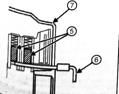
21. Squeeze brushes (5) and hold them in that position with a rod (6) or wire inserted into the hole in the back of the rear bearing (7).
22. Heat up the area around the rear bearing housing to 50-60°C to facilitate installation of the rear bearing into the housing.
23. Install:
- front bearing, pulley and rotor assembly to stator and rear bearing assembly,
- front bearing bolts.
24. Remove the rod or wire holding the brushes.
25. Torque tighten the front bearing bolts (4 Nm).
26. Turn the pulley by hand to check that the rotor turns freely.
27. Check the correct operation of the generator (see "Generator check").
Replacing the voltage regulator
1. Disconnect the front bearing, pulley and rotor assembly from the stator and rear bearing assembly using a flathead screwdriver (see "Rotor replacement").
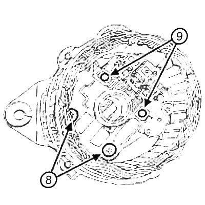
2. Remove screws (8) voltage regulator.
3. Disconnect solder joints (9) voltage regulator and disconnect the brushes and voltage regulator from the bridge rectifier.
Note: After completing the installation of the alternator, perform a voltage regulator test by measuring the supply voltage.
4. Remove the voltage regulator.
5. Install the voltage regulator.
6. Solder the voltage regulator connections to the bridge rectifier.
7. Install the voltage regulator bolts.
8. Torque tighten the voltage regulator bolts (4 Nm).
9. Install the front bearing, pulley and rotor assembly on the stator-rear bearing assembly (see "Rotor replacement").
10. Check the correct operation of the generator (see "Generator check").
Brush replacement
1. Disconnect the front bearing, pulley and rotor assembly from the stator and rear bearing assembly using a flathead screwdriver (see "Rotor replacement").
2. Remove the voltage regulator (see "Replacing the voltage regulator").
3. Remove:
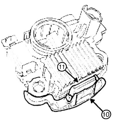
- panel (10),
- protective cover (11).
4. Solder the connections of the brush holder of one brush, then the other.
5. Remove brushes with springs.
6. Check the degree of wear of each brush.
Replace brushes if:
- the working length of the brush is less than 15mm,
- brushes are worn around the edges,
- brushes are cracked.
7. Clean the brushes and their attachments by removing soot particles with a clean cloth.
8. Install brushes with springs.
9. Solder the brush holder connections of one brush, then the other.
10. Make sure the brushes move freely in the brackets.
11. Make sure that the brush springs work correctly and quickly: when you press the brushes down with your finger, they should move freely in the mounts, when you release your finger, they should return to their original position under the influence of the springs.
12.Install:
- voltage regulator (see "Replacing the voltage regulator").
- front bearing, pulley and rotor assembly on the stator - rear bearing assembly (see "Rotor replacement").
13. Check the correct operation of the generator (see "Generator check").
Stator replacement
1. Disconnect the front bearing, pulley and rotor assembly from the stator and rear bearing assembly using a flat-tip screwdriver (see "Rotor replacement").
Note:
- To securely fix the stator winding terminals, use solder with a high melting point (230°С).
- Disconnect quickly (for no more than 5 seconds), using a soldering iron with a power of 180 - 270 V. as overheating of the diode causes damage to it.
2. Unsolder the ends (12) stator windings.
Note: To avoid damage to the stator winding, do not insert the screwdriver further than 2 mm.
3. Remove the stator using a flat head screwdriver.
4. Inspect the winding for discoloration.
5. Check:
- is there a connection between the stator winding and "weight", by measuring the resistance between "weight" stator and winding ends: the resistance must be equal to infinity,
- winding resistance by measuring the resistance of each winding.
The resistance of each winding should be:
- 0.049 - 0.059Ω at 20°C for a 70A generator,
- 0.044 - 0.054Ω at 20°C for a 110A generator.
6. Install the stator on the rear bearing.
Note:
- To securely fix the stator winding terminals, use solder with a high melting point (230°С).
- Disconnect quickly (for no more than 5 seconds), using a soldering iron with a power of 180-270 V, as overheating of the diode causes damage to it
7. Solder the ends of the stator winding.
8. Install the front bearing, pulley and rotor assembly onto the stator-rear bearing assembly (see "Rotor replacement").
9. Check the correct operation of the generator (see "Generator check").
Bridge Rectifier Replacement
1. Disconnect the front bearing, pulley and rotor assembly from the stator and rear bearing assembly using a flathead screwdriver (see "Rotor replacement").
2. Remove:
- stator (see "Stator replacement"),
- voltage regulator (see "Replacing the voltage regulator").
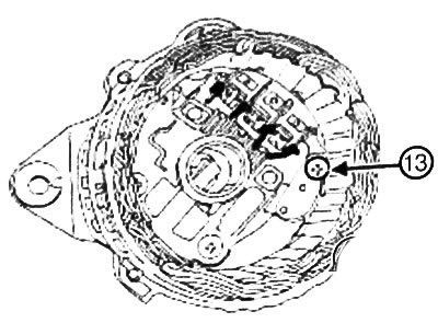
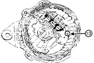
3. Remove the bolt (13) bridge rectifier.
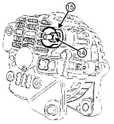
4. Remove:
- nut (14) from terminal B,
- insulator (15),
- bridge rectifier with rear bearing.
5. Check continuity between:
- heat sink (16) and each of the three terminals (17),
- negative contact (18) heat sink and each of the three terminals (17).
If diode conduction is present in both directions, the diode is short-circuited: replace the bridge rectifier.
If there is no diode conduction in both directions, there is an open circuit in the diode: Replace the bridge rectifier.
6. Install:
- bridge rectifier on the rear bearing,
- insulator,
- terminal nut B.
7. Tighten the terminal nut to a torque of 16 Nm.
8. Screw in the bridge rectifier screw.
9. Tighten the bridge rectifier bolt to 4 Nm.
10. Install:
- voltage regulator (see "Replacing the voltage regulator").
- stator (see "Stator replacement"),
- front bearing, pulley and rotor assembly on the stator - rear bearing assembly (see "Rotor replacement").
11. Check the correct operation of the generator (see "Generator check").