
Removing
Place the car on a two post lift.
Disconnect the battery.
Remove the engine undertray.
Drain the engine oil.
Remove:
- upper engine covers;
- oil dipstick;
- front wheels;
- fenders.
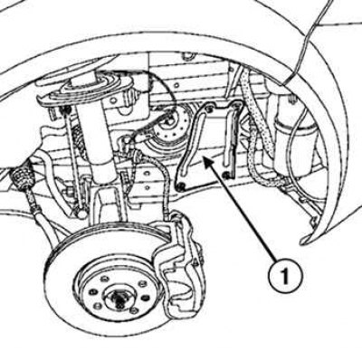
Pic. 2.30. Removing the side reinforcements of the subframe: 1 - side reinforcements of the subframe
Remove the side reinforcements of the subframe (pic. 2.30).
Secure the engine cooling radiator with a tether strap to the top cross member.
Note. When installing, make sure that the safety belt does not pinch the hoses of the cooling system.
Loosen the nuts and bolts of the subframe.
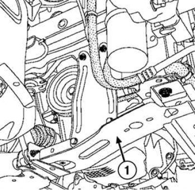
Pic. 2.31. Removing the subframe: 1 - subframe
Remove the subframe (pic. 2.31).
Unscrew the bolts securing the flange of the wheel drive shaft to the intermediate support.
Unscrew the bolts securing the intermediate support to the engine crankcase.
Remove the bolt securing the engine oil pan to the multifunction bracket.
Loosen the engine sump bolts.
Remove the engine oil pan.
Installation
Clean the mating surfaces with DECAPJOINT to dissolve adhering gasket residue.
Apply the compound to the surface to be cleaned, wait about ten minutes, then remove the excess with a wooden spatula.
Attention! Mounting surfaces must be clean, dry and free of oil (leave no fingerprints).
Attention! If too much sealant is applied, then when the fastening bolts are tightened, its excess will be squeezed out. The ingress of sealant into working fluids can lead to damage to some components and assemblies (engine, radiator, etc.).
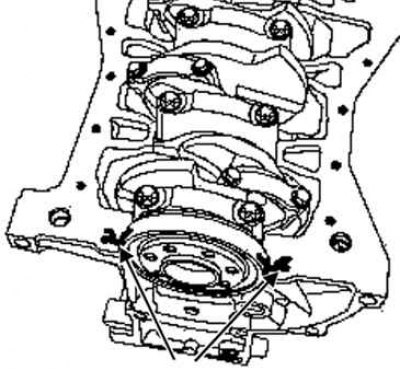
Pic. 2.32. Places for applying silicone sealant
Apply four dots of silicone sealant with a diameter of 5 mm, in the places indicated by the arrows in Figure 2.32.
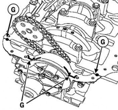
Pic. 2.33. Places for applying silicone sealant to the interface of the front cover
Apply two drops of silicone sealant with a diameter of 7 mm to the mating of the front cover with the cylinder block (pic. 2.33).
Install the oil separator on the cylinder block.
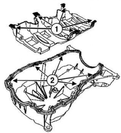
Pic. 2.34. Checking the installation of the engine oil pan: 1 - tongues of the oil softener; 2 - pallet grooves
When installing the engine crankcase pan, check that the tongues of the oil separator fit into the grooves of the pan (pic. 2.34).
The planes of the cylinder block and the sump on the flywheel side are aligned to prevent deformation of the clutch housing.
Install the engine oil pan with a new gasket.
Install the engine oil pan bolts without tightening them.
Install the engine oil pan bolts from the gearbox without tightening them.
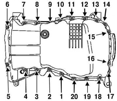
Pic. 2.35. The procedure for tightening the engine sump bolts
Tighten the bolts in the order shown in Figure 2.35 to the required torque.
Table 2.4. The moments of an inhaling of bolts of fastening of the pallet crankcase of the engine
| Element | Tightening torques, Nm |
| Bolts of fastening of the pallet crankcase | 14 |
| Bolts of fastening of the pallet of a crankcase of the engine in a transmission | 44 |
| bolts securing the engine oil pan to the multifunctional bracket | 21 |
| subframe mounting bolts | 105 |
| subframe mounting nuts | 21 |
| wheel bolts | 110 |
| battery cover fasteners | 4 |