
Attention! Together with the belt, be sure to replace the tension and bypass rollers.
Note. The procedure for removing and installing the timing belt for engines with or without a camshaft dephaser is the same.
Removing
Place the car on a two post lift.
Disconnect the battery.
Remove the battery.
Remove the right front wheel.
Remove the right front fender liner.
Remove the engine top covers.
Install fixtures (Mot. 1453) And (Mot. 1453-01) with restraint straps.
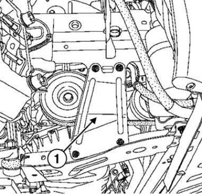
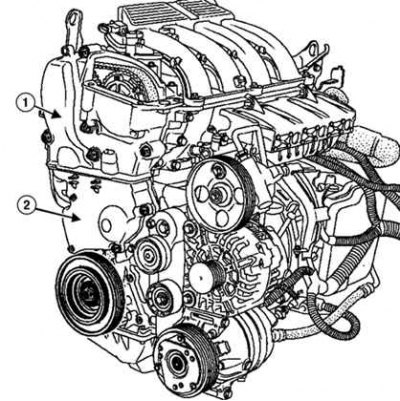
Pic. 2.54. Removing the right side reinforcement of the radiator frame cross member: 1 - amplifier
Remove the right side reinforcement of the radiator frame cross member and the lower jet rod (pic. 2.54).
Disconnect the connectors, disconnect the hood latch cable.
Remove the holder.
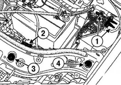
Pic. 2.55. Removing the bypass roller using a special tool: 1 - connectors; 2 – a cable of a drive of the lock of a cowl; 3 - holder; 4 – a bolt of fastening of a bumper
Loosen the mounting bolt and remove the front bumper (pic. 2.55).
Disconnect the washer tubes.
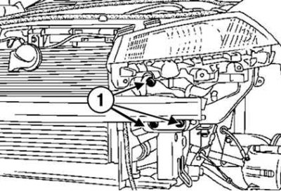
Pic. 2.56. Removing the bypass roller using a special tool: 1 - fastening bolts
Loosen the bolts securing the front panel of the body (pic. 2.56)
Remove the front body panel.
Remove the right front wheel drive shaft.
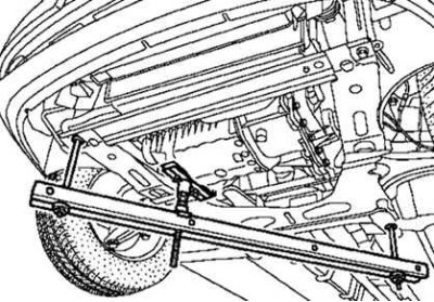
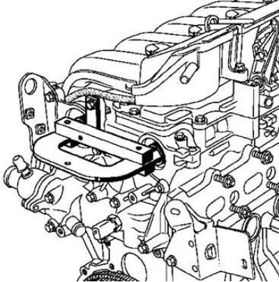
Pic. 2.57. Installing the fixture with fastening straps
Install fixture (Mot. 1672) with fastening straps (pic. 2.57).
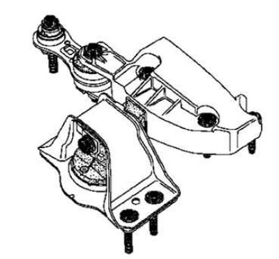
Pic. 2.58. Marking of pendulum suspension supports
Mark the position of the pendulum support in relation to the body (pic. 2.58).
Remove the pendulum support.
Note. Take care not to deform the air conditioning piping.
Note. Remove the accessory drive belt.
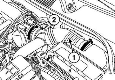
Pic. 2.59. Removing the outlet air line of the air filter and throttle body: 1 - the outlet air duct of the air filter; 2 - throttle valve block
Remove the air cleaner outlet duct, throttle body and wiring harness from the lifting lug (pic. 2.59).
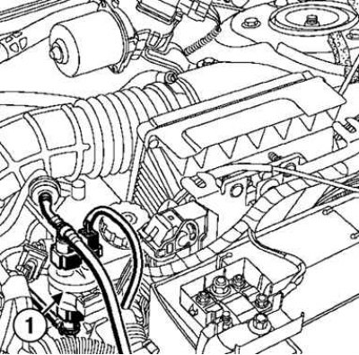
Pic. 2.60. Removing the canister purge solenoid valve: 1 - solenoid valve
Remove the canister purge solenoid valve (pic. 2.60).
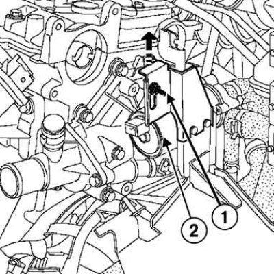
Pic. 2.61. Release of the electric water pump: 1 - fastening nut; 2 - water electric pump
Unscrew the nut, pull the electric water pump mounting post and move it aside (pic. 2.61).
Pic. 2.62. Removing the hole plug for the TDC lock: 1 - cork
Unscrew the plug from the hole for the TDC lock (pic. 2.62).
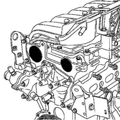
Pic. 2.63. Camshaft plugs
Remove the camshaft caps (pic. 2.63).
First installation of valve timing
Pic. 2.64. Camshaft Alignment
Turn the engine clockwise (viewed from the timing side) so that the grooves of the camshafts are directed downwards and are almost in a horizontal position, as shown in Figure 2.64.
Pic. 2.65. Installing the TDC lock
Insert TDC lock (Mot. 1054) so that it is between the balancing hole and the crankshaft blocking groove (pic. 2.65).
Rotate the crankshaft in the same direction so that the TDC lock (Mot. 1054) was in the locking groove of the crankshaft.
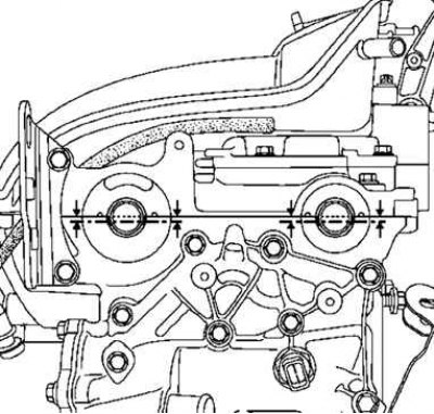
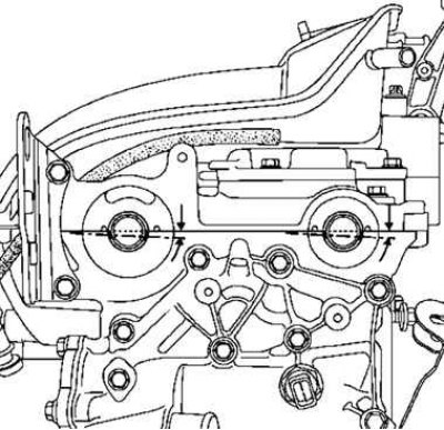
Pic. 2.66. Offset of camshaft grooves in axial direction
In the installation position, the grooves of the camshafts are located horizontally and axially shifted down, as shown in Figure 2.66.
Remove the TDC lock.
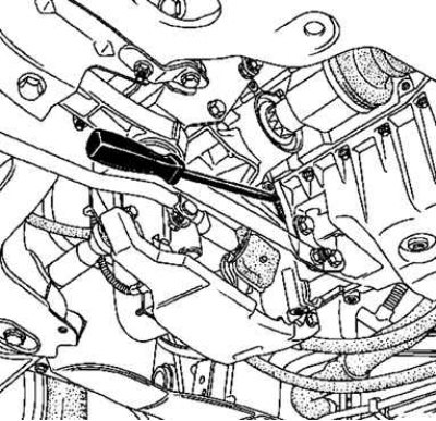
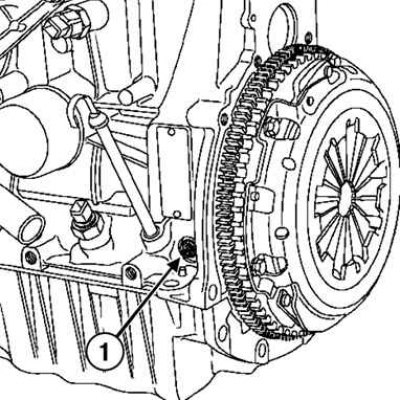
Pic. 2.67. Engine flywheel lock
Remove the flywheel guard and crankshaft pulley by blocking the engine flywheel with a screwdriver (pic. 2.67).
Install the top dead center clamp (Mot 1054).
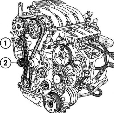
Pic. 2.68. Removing the timing cover: 1 - top cover; 2 - bottom cover
Remove the upper and lower timing covers (pic. 2.68).
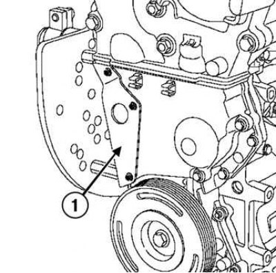
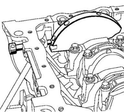
Pic. 2.69. Removing the heat shield: 1 - heat shield
Remove heat shield (pic. 2.69).
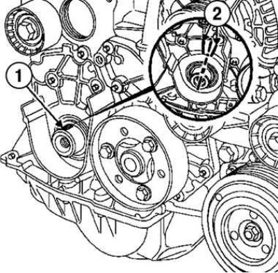
Pic. 2.70. Nut of fastening of an axis of a tension roller: 1 - nut; 2 - bypass roller
Loosen the timing belt by unscrewing the tensioner axle nut (pic. 2.70).
Remove the idler pulley, timing belt and crankshaft sprocket.
Attention! Never turn the engine crankshaft in the opposite direction to the direction of rotation.
Second camshaft setting
Check that the gear ring of the inlet camshaft dephaser is securely fixed (crown cannot be turned left or right).
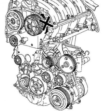
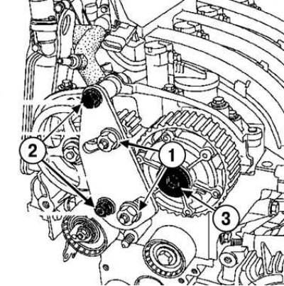
Pic. 2.71. Fixing the ring gear of the phase regulator of the camshaft
Install on special tool (Mot. 1509) gear (Mot. 1509-01).
Pic. 2.72. Spacer installation: 1 - remote bushing; 2 - hairpin
Put on the tool spacer (Mot. 1509–01) on a hairpin (pic. 2.72).
Pic. 2.73. Attaching the top bolt to the spacer bush: 1 - top bolt; 2 - remote bushing
Install the top bolt by placing the spacer (Mot. 1509–01) between fixture and cylinder head cover (do not fully tighten the bolt) (pic. 2.73).
Tighten the bolt and collar nut.
Suspension gear tool (Mot. 1509) to the camshaft pulleys.
Tighten the nuts securing the toothed pulleys (80 Nm).
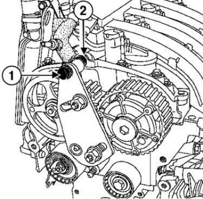
Pic. 2.74. Removing the plug of the phase regulator of the intake camshaft: 1 - bolt and nut with collar; 2 - nuts for fastening toothed pulleys; 3 - phase regulator plug
Remove the intake camshaft dephaser plug (pic. 2.74).
Remove the bolt securing the intake camshaft dephaser.
Remove the exhaust camshaft sprocket nut and tool (Mot. 1509).
Remove the camshaft pulleys.
Loosen the stud and nut if necessary.
Install fixture (Mot. 1509) with gears (Mot 1509-01).
Tighten the bolt and collar nut.
Move the tool gears until they touch the camshaft pulleys.
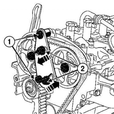
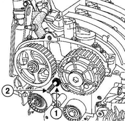
Pic. 2.75. Tightening the toothed pulley studs: 1 - nut with collar; 2 - studs for fastening toothed pulleys
Tighten the toothed pulley studs (80 Nm) (pic. 2.75).
Loosen the nuts securing the camshaft pulleys.
Remove fixture (Mot. 1509) and toothed camshaft pulleys.
Install pre-greased camshaft pulleys using old nuts.
With the aid of a device (Mot. 799-01) tighten the nuts to the required torque of 15 Nm.
Attention! When replacing the timing belt, be sure to replace the crankshaft pulley, bypass and idler rollers, and the timing and accessory belts.
Install the offset slots horizontally down as shown above by turning the camshafts using the tool (Mot. 799-01).
Pic. 2.76. Fixing the ends of the camshafts
Fix fixture (Mot. 1496) at the ends of the camshafts (pic. 2.76).
Remove the exhaust camshaft sprocket nut and the intake camshaft dephaser pulley bolt.
Turn away nuts of fastening of gear pulleys of camshafts.
Make sure the crankshaft is locked.
Pic. 2.77. Checking the crankshaft lock: 1 - groove of the crankshaft; 2 - ribs
The groove of the crankshaft must be between the two ribs (pic. 2.77).
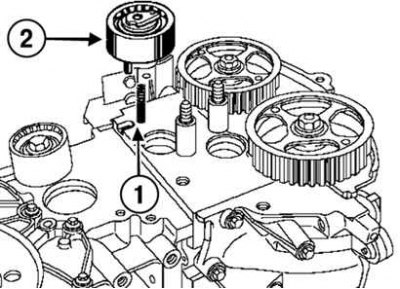
Pic. 2.78. Tension roller installation: 1 - protrusion; 2 - groove
Install the tension roller, placing its protrusion in the groove (pic. 2.78).
Install the crankshaft sprocket, timing belt and idler pulley.
Torque tighten (50 Nm) idler roller bolt.
Belt tension check
Attention! Do not rotate the tensioner counterclockwise.
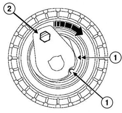
Pic. 2.79. Alignment of marks on the tension roller: 1 - marks; 2 - key
Align the marks on the idler pulley with a 6mm hex wrench (pic. 2.79).
Torque tighten (7 Nm) nut of fastening of an axis of a tension roller.
Install fixtures (Mot. 1509) with gears and (Mot. 1509–01) for locking the camshaft pulleys.
Tighten the bolt and collar nut.
Tighten the nuts securing the toothed pulleys until they touch the camshaft pulleys.
Torque tighten:
- stud nuts for toothed pulleys (80 Nm);
- old intake camshaft dephaser bolt (30 Nm);
- exhaust camshaft pulley nut (30 Nm).
Pic. 2.80. Setting the position of the camshaft pulleys relative to the bearing caps: 1 - alignment marks
Remove fixture (Mot. 1509) with fixture (Mot. 1509-01).
Install fixture (Mot. 1509) for locking the camshaft pulleys.
Tighten the bolt and collar nut.
Tighten the nuts securing the toothed pulleys until they touch the camshaft pulleys.
Torque tighten:
- stud nuts for toothed pulleys (80 Nm);
- nuts of fastening of gear pulleys of camshafts of inlet and final valves (30 Nm).
Remove fixture (Mot. 1509) with fixture (Mot. 1509-01).
Use a pencil to mark the position of the camshaft pulleys relative to the camshaft bearing caps.
Align the TDC lock (Mot. 1054) and a tool for fixing the camshafts (Mot. 1496).
Rotate the crankshaft two turns clockwise (viewed from the timing side).
Installation
Install the lower and upper timing covers.
Attention! Be sure to replace the mounting bolt and crankshaft pulley.
Block the engine flywheel with a large screwdriver.
Tighten the crankshaft pulley bolt to torque (40 Nm, then tighten by 110°+10°).
Attention! To prevent damage to the crankshaft pulley, do not start the engine unless the accessory drive belt is installed.
Install the accessory drive belt.
Install the top dead center hole plug with a small amount of sealant.
Install new intake camshaft and exhaust camshaft plugs.
Install the remaining components in the reverse order of removal.
Table 2.8. Necessary fixtures and special tools
| Marking | Name |
| Mot. 1453 | Adjustable support bar with retaining straps for hanging the engine |
| Mot. 1453-01 | Additional nut with handle for engine jack Mot. 1453 |
| Mot. 1672 | Engine maintenance tool |
| Mot. 1054 | TDC lock |
| Mot. 1509 | Tool for fixing the camshaft pulleys |
| Mot. 1509-01 | Adapter kit Mot. 1509 |
| Mot. 799-01 | Camshaft pulley retainer |
| Mot. 1496 | Camshaft Locking Tool |
| Mot. 1487 | Camshaft cover installer (diameter 57 mm) |
| Mot. 1448 | Clamp pliers with remote grip |
Table 2.7. Tightening torques when removing and installing the timing belt
| Element | Tightening torques, Nm |
| Nuts of fastening of toothed pulleys | 80 |
| Toothed pulley studs | 80 |
| Bypass roller mounting bolt | 50 |
| Nut of fastening of an axis of a tension roller | 7 |
| Nuts of hairpins of fastening of toothed pulleys | 80 |
| Bolt of fastening of the phase regulator of a camshaft of inlet valves | 30 |
| Nut of fastening of a pulley of a camshaft of final valves | 30 |
| Nuts of fastening of gear pulleys of camshafts of inlet and final valves | 30 |
| Nuts of fastening of toothed pulleys | 80 |
| Nut of fastening of an axis of a tension roller | 28 |
| Bolt of fastening of the phase regulator of a camshaft of inlet valves | 30 |
| Bolt of fastening of the phase regulator of a camshaft of inlet valves | 100 |
| Plug of a pulley of a camshaft of final valves | 25 |
| Nut of fastening of a gear pulley of a camshaft of final valves | 86°±6° |
| Nuts of fastening of gear pulleys of camshafts of final and final valves | 86°±6° |
| Nuts of fastening of gear pulleys of camshafts of final and final valves | 30, then tighten 86°±6° |
| Bolt of fastening of a pulley of a cranked shaft moment | 40, then tighten by 110°±10° |
| M6 bolts for fastening the lower cover of the timing drive | 80 |
| M8 bolts for fastening the lower cover of the timing drive | 20 |