
Note. To remove the air supply pipe from the air-to-air cooler (F4R engine) disconnect the hose using the tool (Sag. 1363).
Do not use brake cleaners or other cleaning agents.
Wipe the air-to-air cooler seat and hose with a lint-free cloth.
If the hose is not being replaced, reinstall the clamp.
If the nozzle and/or air-to-air cooler are damaged, be sure to replace them.
Failure to follow this procedure may result in air leakage or hose disconnection.
Removing
Place the car on a two post lift.
Remove the engine top covers.
Remove the front wheels.
Remove the left and right fender liner.
Remove the engine undertray.
Drain the gearbox oil.
Drain the engine oil.
Disconnect the battery.
Drain the refrigerant circuit from the filling station.
Remove the side reinforcements of the subframe and the front bumper.
Disconnect the hood latch cable.
Disconnect the washer tubes.
Drain the liquid from the engine cooling system.
Unscrew the fastening bolts and remove the front panel of the body.
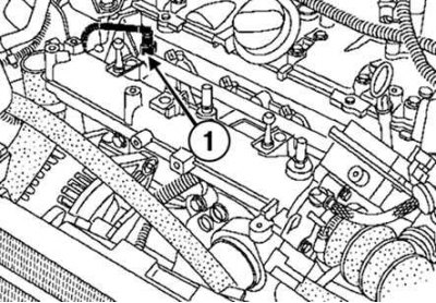
Pic. 2.92. Disconnecting the fuel supply line: 1 - fuel line
Disconnect the fuel supply line from the fuel rail (pic. 2.92).
Disconnect the supply hose from the radiator of the engine cooling system using the tool (Mot. 1202-01 or Mot. 1202-02 or Mot. 1448).
Disconnect the wire blocks from the electric fan of the engine cooling system.
Disconnect the engine cooling fan wiring harness.
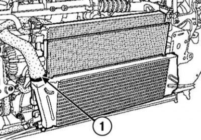
Pic. 2.93. Disconnecting the air line from the air-to-air cooler: 1 - air duct
Disconnect the air line from the air-to-air cooler (pic. 2.93).
Disconnect:
- block of wires from the boost pressure sensor;
- block of wires from the air temperature sensor;
- block of wires from the resistor of the electric fan of the engine cooling system.
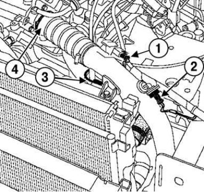
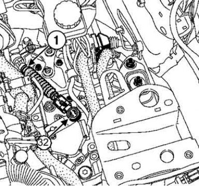
Pic. 2.94. Disconnecting the wire blocks of the boost pressure and air temperature sensors, the resistor of the electric fan of the engine cooling system: 1 - boost pressure sensor; 2 – air temperature sensor; 3 - resistor of the electric fan of the engine cooling system; 4 - air duct
Move aside the air line (pic. 2.94).
Remove the air filter outlet duct.
Disconnect the expansion tank hoses from the engine cooling system radiator.
Disconnect the pressure sensor connector on the condenser air conditioning downpipe.
Remove the refrigerant lines from the condenser and the refrigerant lines between the compressor and the receiver-drier.
Note. Be sure to plug the piping and reducer openings to prevent moisture from entering the system.
Remove the engine cooling system radiator assembly with condenser.
Disconnect the ECU connectors.
Turn away bolts of fastening and remove the shelf under the rechargeable battery.
Set aside the canister purge solenoid valve.
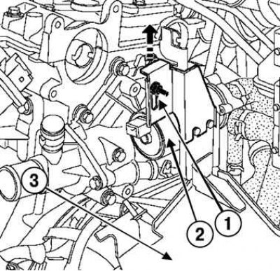
Pic. 2.95. Removing the water pump: 1 - bolt; 2 - bracket; 3 - water electric pump
Unscrew the bolt, pull the water pump mounting post and, moving the water pump aside, remove the water pump bracket (pic. 2.95).
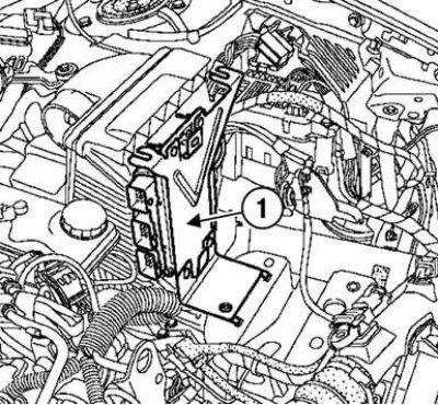
Pic. 2.96. Removing the ECU: 1 - ECU
Remove the ECU assembly with the bracket (pic. 2.96).
Remove the air filter housing.
Disconnect the relay harness connectors.
Disconnect «mass» tire.
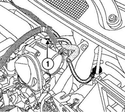
Pic. 2.97. Removing the suction hose of the vacuum brake booster: 1 - hose
Remove the brake booster vacuum hose (pic. 2.97).
Disconnect the downstream oxygen sensor connector.
Disconnect select and shift cables from transmission.
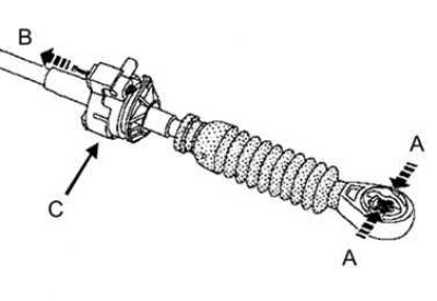
Pic. 2.98. Disconnecting the gear lever cable
Disconnect the cables from the levers on the gearbox by squeezing the tip of the cable at points A, pull the latch in direction B and lift the cables at point C, as shown in Figure 2.98.
Pic. 2.99. Removing the multifunction switch cable ball end: 1 - ball tip
Remove the ball end of the multifunction switch cable (pic. 2.99).
Remove the multifunction switch cable by releasing the cable sheath stopper.
Place a rag under the master cylinder.
Remove the retainer from the union on the intermediate branch pipe of the master cylinder.
Disconnect the tube from the working cylinder. Insert the plugs into the holes.
Remove the supply pipe to the working cylinder.
Remove the right front wheel drive shaft.
Remove the left front wheel drive shaft.
Remove the fastening parts of the exhaust pipe of the exhaust system,
Remove the upper and lower jet rods.
Remove the subframe.
Install a hydraulic crane with a hoist or chain.
Mark the position of the engine pendulum mount relative to the body.
Remove the engine mount.
Remove the transmission swing arm support.
Rotate the engine and gearbox assembly and remove it.
Installation
Install the engine and gearbox assembly to the vehicle.
Install:
- support of the pendulum suspension of the engine;
- support pendulum suspension gearbox;
- lower jet thrust;
- upper jet thrust;
- drive shaft of the left front wheel;
- right front wheel drive shaft.
Install the remaining components in the reverse order of removal.
Torque tighten:
- bolts of the upper fastening of the front panel of the body (21 Nm);
- bolts of the lower fastening of the front panel of the body (44 Nm);
- front subframe bolt (105 Nm);
- rear subframe bolt (21 Nm);
- wheel bolts (110 Nm).
Add brake fluid to the reservoir.
Bleed air from hydraulic clutch.
Fill the gearbox with oil.
Fill the engine with oil.
Fill the cooling system with fluid.
Charge the refrigeration circuit with refrigerant using a filling station.
Note. Attach the brake hose and ABS speed sensor wires correctly.
Note. Do not kink the brake hose.
Connect the battery.
Remove air from the cooling system.
Torque tighten (4 Nm) battery cover bolts.