
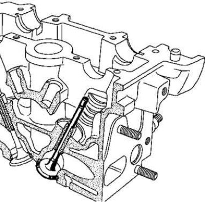
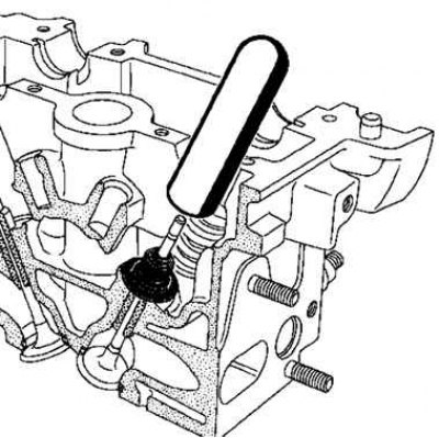
Pic. 2.124. Installing the valve in the cylinder head
Insert the valve into the cylinder head (pic. 2.124).
Put on the tip of the tool (Mot. 1511) on the valve stem (the inner diameter of the tip must be equal to the diameter of the rod).
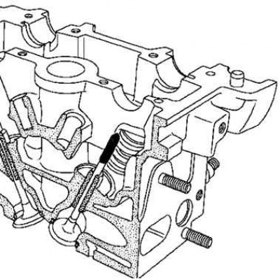
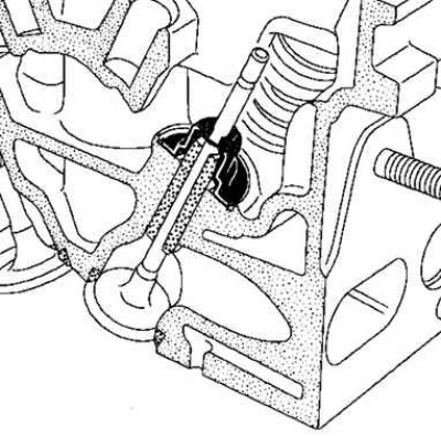
Pic. 2.125. Valve seat retention
Keep the valve pressed against the seat (pic. 2.125).
Install the oil seal (not oiled) on the tip.
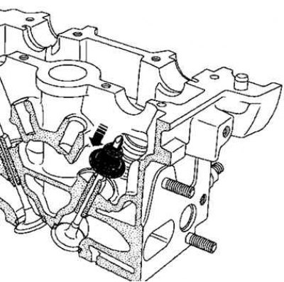
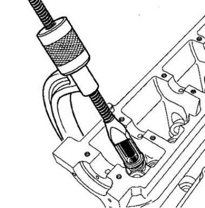
Pic. 2.126. Installing the oil seal
Slide the slinger cap until it passes over the tip (pic. 2.126).
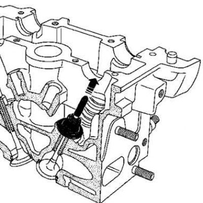
Pic. 2.127. Removing the Tool Tip
Remove tip (pic. 2.127).
Pic. 2.128. Installing the mandrel on the oil seal
Install the mandrel on the oil seal (pic. 2.128).
Note. The inner diameter of the mandrel must match the diameter of the valve stem. In addition, the lower part of the mandrel should partially abut against the slinger cap, which serves as a support washer for the valve spring.
Pic. 2.129. Pressing on the oil seal
Press on the slinger cap by tapping the top of the mandrel with the palm of your hand until the slinger cap contacts the cylinder head (pic. 2.129).
Repeat the above steps for all valves.
Pic. 2.130. Valve spring installation
Install springs and spring plates (pic. 2.130).
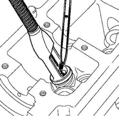
Pic. 2.131. Installation of crackers
Insert crackers with curved tongs (pic. 2.131).
Install the thermostat block with a new gasket on the cylinder head.
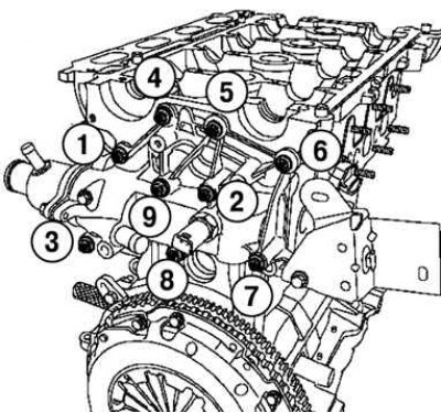
Pic. 2.132. The order of tightening the bolts of the thermostat housing
Tighten in the order shown in figure 2.132 with the required moment (10 Nm) bolts of fastening of the block of the thermostat on a head of the block of cylinders.
Install the exhaust manifold with a new gasket.
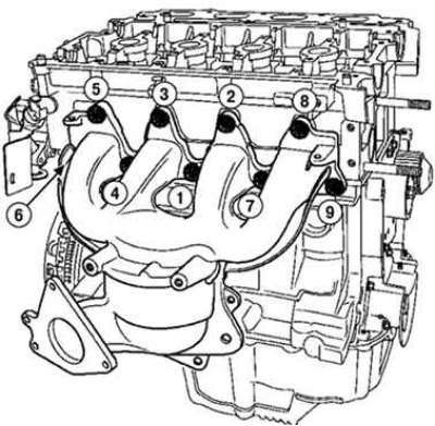
Pic. 2.133. The procedure for tightening the nuts of the exhaust manifold mounting studs
Tighten in the order specified in drawing 2.133 the required moment (23 Nm) exhaust manifold nuts.
Install the exhaust manifold heat shield.
3torque (1 Nm) exhaust manifold heat shield bolts.
Attention! Make sure the exhaust manifold heat shield is securely seated between the oxygen sensor and the manifold (to avoid overheating which could destroy the wiring of the upstream oxygen sensor).
Torque tighten (4.5 Nm) oxygen sensor with tool (Mot. 1495).
Install the inner timing case spacer.
Install the injector body shims with a new gasket.
Install the oxygen sensor.
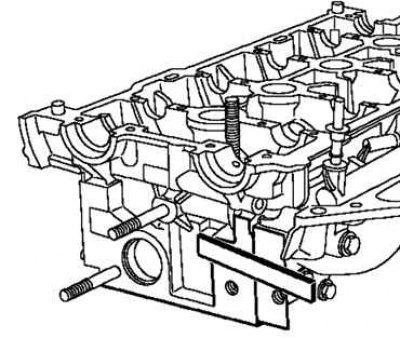
Pic. 2.134. Alignment of the injector body gasket
Align the lining of the injector bodies with respect to the cylinder head (from the timing drive) (pic. 2.134).
Align the mating planes of the lining of the injector bodies with respect to the cylinder head.
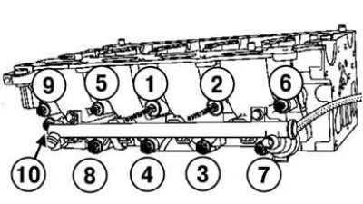
Pic. 2.135. The order of tightening the bolts for fastening the lining of the injector housings
Tighten in order to the correct torque (21 Nm) injector housing mounting bolts (pic. 2.135).