
The system includes:
- low pressure fuel pump (1. fig. 4.43). located between the intake tract and the fuel filter.
- fuel filter (2);
- high pressure fuel pump (3);
- high pressure regulator (4), installed on the injection pump;
- fuel distribution line (5) with fuel pressure sensor.
- fuel supply system refill valve (6). open during normal engine operation;
- fuel cooler (7);
- four electromagnetic injectors;
- sensors;
- injection system control unit.
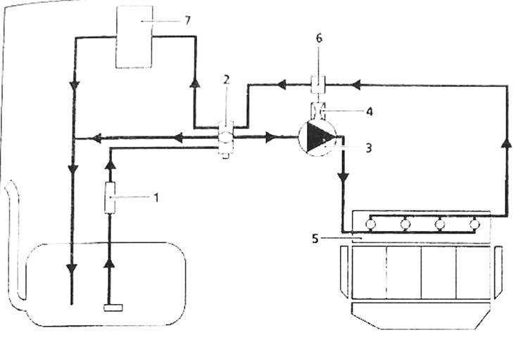
Pic. 4.43. Fuel system diagram: 1 - low pressure fuel pump; 2 - fuel filter; 3 - high pressure fuel pump; 4 - high pressure regulator; 5-fuel distribution line; 6 - valve for refilling the fuel supply system; 7 - fuel cooler
Disassembly of the high pressure fuel pump and injectors is not provided. High pressure direct injection system «Common Rail» is a sequential injection system operating on the principle of distributed injection systems for gasoline engines.
This new injection system, thanks to its pre-injection method, reduces engine noise, particulate matter and toxic gases in the exhaust gases and significantly increases engine torque, starting from low engine speeds.
The low pressure fuel pump, or booster pump, supplies fuel through the fuel filter to the high pressure fuel pump at a pressure of 2 to 4 bar.
The high pressure fuel pump supplies high pressure fuel into the fuel rail. The pressure regulator installed on the injection pump changes the amount of fuel pressure according to commands from the injection system control unit. From the fuel distribution line, fuel is supplied to the injectors through steel fuel lines.
The injection system control unit performs the following functions:
- determines the amount of injection pressure necessary for normal engine operation and sends appropriate signals to the pressure regulator. It controls the amount of pressure based on an analysis of the values produced by the fuel pressure sensor installed on the fuel distribution line;
- determines the injection time required to supply a sufficient amount of fuel and the moment when injection begins;
- after determining these two values, it individually controls the operation of each injector by supplying electrical signals.
The amount of fuel supplied to the engine is determined depending on:
- duration of supply of the control signal to the injector;
- nozzle opening and closing speeds;
- the stroke value of the nozzle valve needle;
- hydraulic performance of the nozzle;
- pressure in the fuel distribution line, regulated by the injection system control unit.
The system provides fuel injection at pressures up to 1350 bar. Before performing any work on the fuel system, make sure there is no pressure in the fuel distribution line.
The specified tightening torques for the threaded connections of the following fuel system components must be strictly observed:
- high pressure fuel lines;
- when screwing the injectors into the cylinder head;
- pressure regulator;
- fuel pressure sensor.
When repairing or removing the high-pressure fuel pump, injectors, supply and return fuel lines, to protect against contamination, it is necessary to close the holes with new plugs of the required diameter.
Attention. All removed fuel lines must be replaced.
Replacement of high pressure fuel lines must be done in the following order:
- remove the high pressure fuel line, using another wrench to hold the filter pin on the injector;
- close the holes with safety plugs;
- loosen the tightening of the fuel distribution line bolts;
- install a new high pressure fuel line;
- connect the connections manually;
- tighten the high pressure line fasteners to the required torque;
- tighten the fitting securing the fuel line to the injector to the required torque;
- tighten the fitting securing the fuel line to the high pressure line to the required torque.
When removing the injection pump, it is necessary to replace the fuel return line connected to the injectors.
The fuel temperature sensor is non-removable. It is integral with the fuel return line.
It is prohibited to loosen the high pressure fuel line fittings while the engine is running.
After performing any work related to the fuel system, make sure there are no fuel leaks. Let the engine idle until the electric cooling fan turns on, then increase the engine idle speed several times.
The system is very sensitive to contamination. Contaminants can cause damage or complete failure of the high-pressure injection system or clogging or depressurization of system components. All maintenance work on the fuel system must be carried out in completely clean conditions.
Attention. It is forbidden to wash the engine with a high-pressure jet, because... This can damage the electrical wiring connectors. In addition, moisture can get inside the connectors, which can damage the integrity of electrical circuits
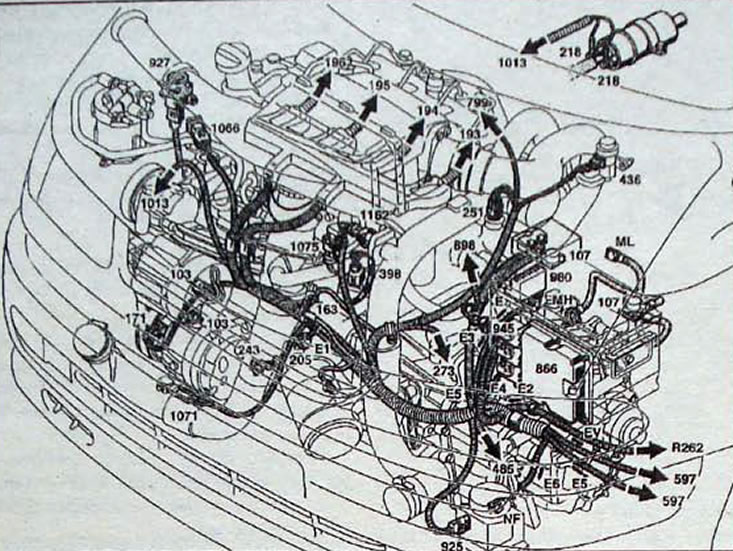
Pic. 4.44. Location of fuel system elements in the engine compartment of a car: 193 - nozzle; 194 - nozzle; 195 - nozzle; 196 - nozzle; 218 - fuel pump; 243 - oil level sensor; 251 - dual-function coolant and engine temperature sensor; 398 - exhaust gas recirculation solenoid valve; 436 - pressure regulator; 799 - air flow sensor; 866 - control unit for the fuel injection system of a diesel engine; 925 - heater connector; 927 - shock sensor; 980 - glow plug relay housing; 1013 - phase sensor; 1071 - turbocharger pressure sensor; 1075 - solenoid valve for cutting off the air supply; 1162 - intake manifold turbulator damper control drive
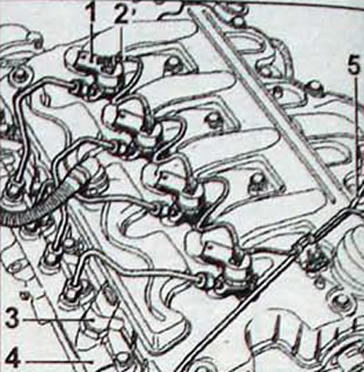
Pic. 4.45. Location of fuel system elements on the engine: 1 - nozzle; 2 - fuel return pipeline from the injectors; 3 - fuel pressure sensor; 4 - fuel distribution line; 5 - fuel supply line to the high pressure fuel pump/fuel distribution line
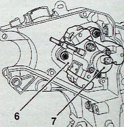
Pic. 4.46. Location of the high pressure fuel pump on the engine (6) and fuel pressure regulator (7)