
Removal
- When removing the power unit, the following special tools must be used:
- universal support Mot. 1390;
- a device for unlocking quick-release connections of the Mot 1410 air conditioning system;
- a wrench for unscrewing the fittings securing the hoses to the steering mechanism Dir. 1282-01 and Dir. 1282-02.
- Place the vehicle on a two-post lift and secure it with safety straps.
- Disconnect the wires from the battery terminals and remove the battery.
- Use the charging station to discharge the refrigerant from the air conditioning circuit.
- Remove the engine oil pan protection.
- Remove the front wheels, front wheel arch mud guards, wheel arch mud guards and front bumper.
- Remove the front wheel drive shafts.
- Remove the coolant expansion tank cap.
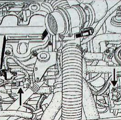
- Drain the working fluid from the power steering system using the tool Dir. 1282-01 disconnect the low pressure hose from the cooler and the high pressure hose (bottom hose) power steering from steering gear (pic. 415). Take measures against leakage of working fluid.
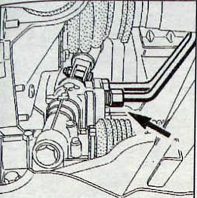
Pic. 4.15. Location of the hose through which it is necessary to drain fluid from the power steering
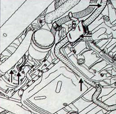
- Disconnect the lower hose from the radiator and drain the coolant to the cooling systems (pic. 4.16).
Pic. 4.16. Place where the lower hose is disconnected from the radiator
- Remove the air filter housing.
- Disconnect the air conditioning compressor pipe fittings.
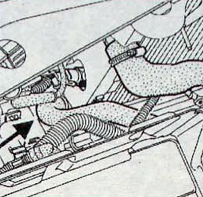
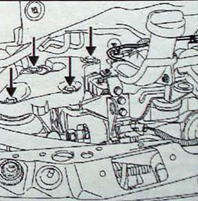
- Remove the auxiliary heater heater exhaust system assembly (pic. 4.17).
Pic. 4.17. Arrangement of elements of the auxiliary heater heater exhaust system
- Remove the exhaust system pre-catalytic converter.
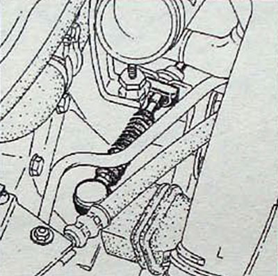
- Remove the jet thrust (pic. 4.18).
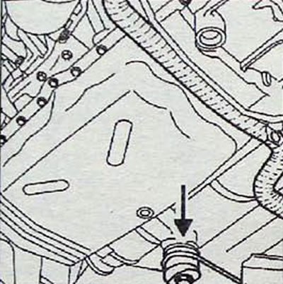
Pic. 4.18. Engine mount torque rod location
- Disconnect the gear shift cables from the gearbox (pic. 4.19, 4.20).
Pic. 4.19. Location of the gear shift cable on the gearbox
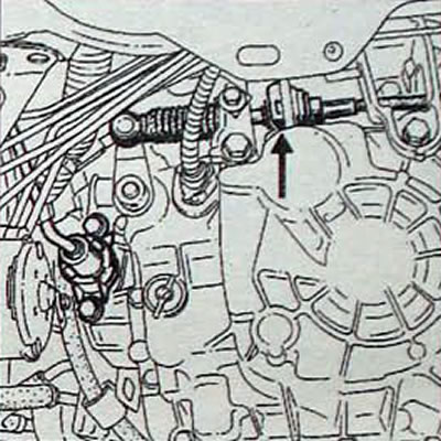
Pic. 4.20. Attaching the gear selection cable to the gearbox
- Remove the radiator trim strip.
- Remove the bolts (C and D. fig. 4.21) and remove the radiator trim.
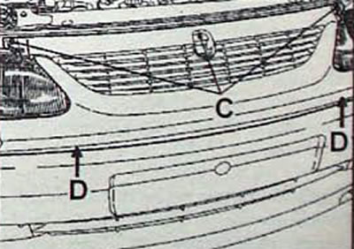
Pic. 4.21. Bolt Location (C and D) radiator trim fastenings
- Remove the left headlight unit.
- Disconnect the wiring harness from the holder located in the engine control sub-unit (pic. 4.22)
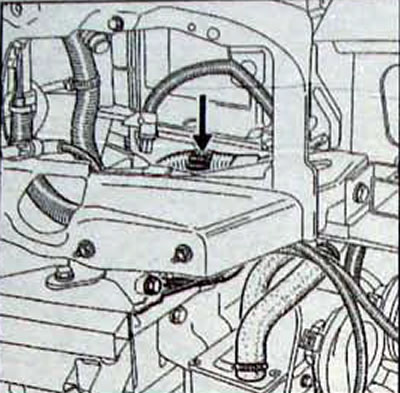
Pic. 4.22. Wiring Harness Holder Location
- Mark the location and disconnect the connectors from the junction box in the engine compartment.
- Disconnect the wire connector from the holder on the shelf under the battery and the holder of the turbocharger pressure regulator control solenoid valve (pic. 4.23).
Pic. 4.23. Location of connectors and turbocharger pressure regulator control valve
- Using a clamp, clamp the supply line of the clutch master cylinder (at the brake fluid reservoir).
- Open the air bleed valve on the clutch slave cylinder (A. fig. 4.24). while holding the fitting from turning with another wrench.
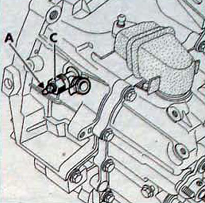
Pic. 4.24. Ventilation valve location (A) on the fitting (WITH) clutch slave cylinder
On the left side of the car
- Disconnect the high pressure pipe fitting of the clutch slave cylinder and disconnect the pipe from the holders.
- Disconnect the cooling system hoses. going from the engine to the expansion tank and to the interior heater radiator.
On the right side of the car
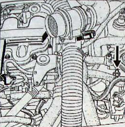
- Disconnect the supply connections (1. fig. 4.25) and drain (2) high pressure pump fuel lines from the fuel filter. In this case, be sure to plug the holes in the fuel lines and filter with plugs of the required size from the Cat kit... No. 77 01 206 381.
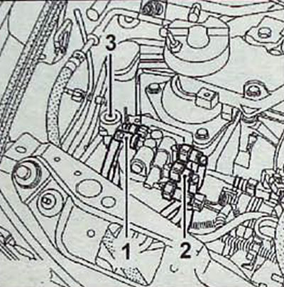
Pic. 4.25. Supply disconnect points (1) and drain (2) high pressure pump fuel lines from fuel filter and connector location (3) inertia switch
- Disconnect the connector from the inertia switch.
- Disconnect the low pressure hose of the air conditioning system from the mounting tab on the throttle body.
- From the underside of the car
- Disconnect the connector from the fuel priming pump and place the disconnected wires over the engine (pic. 4.26).
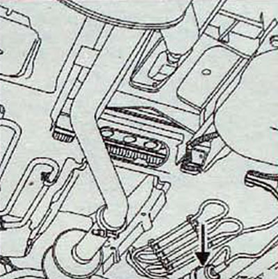
Pic. 4.26. Location of the fuel priming pump
- Prepare the universal support Mot. 1390 and, together with an assistant, install it under the power unit (pic. 4.27. 4.28).
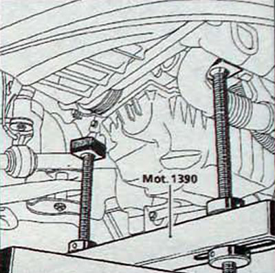
Pic. 4.27. Position of the two universal support legs Mot. 1390 under the power unit
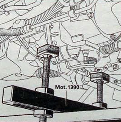
Pic. 4.28. Position of the two universal support legs Mot. 1390 under the power unit
- Remove the right engine pendulum mount casing and the engine pendulum travel limiter rod. located behind the suspension housing (pic. 4.29).
Pic. 4.29. Location of the right engine pendulum mounting bolts
- Unscrew the nut securing the left engine mount rod (pic. 4.30.)
Pic. 4.30. Location of the left engine mount rod mounting nut
- Carefully lift the vehicle over the engine while remaining on the universal support. Be careful when lifting the car. so that the transmission control drive cables are not pinched or damaged.
Installation
- Installation is carried out in the reverse order of removal, taking into account the following.
- Position the transmission control cables in place.
- Lower the engine and transmission assembly into the engine compartment.
- Make sure the gearbox is positioned correctly relative to the engine frame.
- Install the power unit on a pendulum suspension.
- Tighten all screws, nuts and bolts to the specified torques.
- Press the brake pedal several times to bring the pistons into contact with the brake pads.
- Restore the functionality of all devices whose operation was disrupted as a result of disconnecting the wires from the battery terminals.
- Use the charging station to charge the air conditioning circuit with refrigerant. Amount of R134a refrigerant for charging: 800±20 g.
- Fill the engine cooling system with coolant.
- Pour fluid into the power steering hydraulic drive and remove air from it.
- Bleed the hydraulic drive through the air bleed valve installed on the connecting pipe of the clutch slave cylinder. If the fitting is damaged, the clutch slave cylinder must be replaced, which will require removing and installing the gearbox.
- When removing air, in order not to damage the working cylinder and fitting, use a 19 mm socket wrench to hold the fitting from rotating while unscrewing and tightening the valve to remove air, (pic. 4.24).