
Removal
When replacing the timing belt, the following special tools must be used:
- support for power unit Mot. 1390;
- Top dead center lock Mot. 1536;
- device for adjusting and fixing the intake camshaft Mot. 1534;
- device for adjusting the position and fixing the exhaust camshaft Mot. 1537.
Disconnect the cable from the negative terminal of the battery.
If necessary, place the vehicle on a two-post lift.
On the right side of the car, remove the noise insulation of the side member.
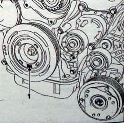
Pic. 4.2. TDC mark location (1) on the crankshaft pulley
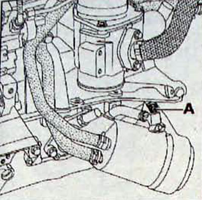
Pic. 4.3. Plug location (A), covering the hole for installing the crankshaft clamp
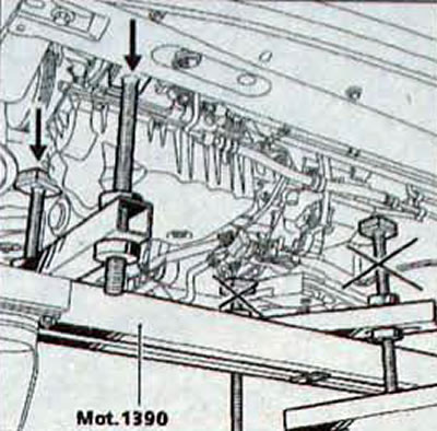
Pic. 4.4. Installing the right universal support shoes Mot. 1390 for the power unit
Pic. 4.5. Location of the lower timing case
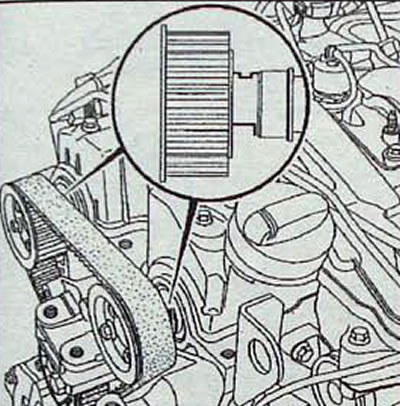
Pic. 4.6. Position of the camshaft grooves when installing the piston of the 1st cylinder at TDC
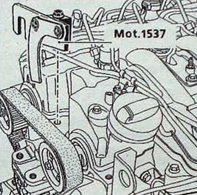
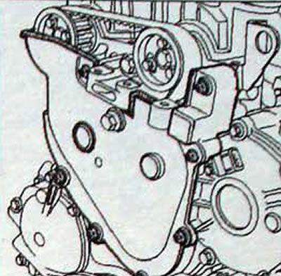
Pic. 4.7. Installation of tool Mot. 1537 for fixing the exhaust camshaft
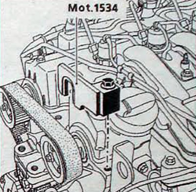
Pic. 4.8. Installation of tool Mot. 1534 for fixing the intake camshaft
- Remove the pendulum suspension travel limiter rod.
- Turn the steering wheel all the way to the right.
- Remove the front right wheel arch mudguard.
- By label (1, fig. 4.2) On the crankshaft pulley, set the engine crankshaft to the TDC position of the piston of the 1st cylinder, unscrew the plug (A, fig. 4.3) and use the lock to block the crankshaft from turning.
- Install universal support Mot. 1390 under the power unit, bringing only its right shoes under the engine, while lowering both left unused shoes as low as possible (Fig 4.4).
- Remove the upper casing of the right engine pendulum mount (pic. 4.30).
- Remove the timing case and lower casing (pic. 4.5).
- Check the position of the camshaft grooves, which should be in the position shown in Figure 4.6.
- Install the camshaft locking tools and carefully tighten them to the cylinder head (pic. 4.7, 4.8).
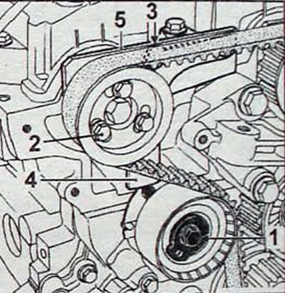
- Loosen the bolt securing the timing belt tension roller, which will loosen the belt tension.
- Unscrew the three bolts securing the pulley to the hub and remove the exhaust camshaft pulley.
- Remove the timing belt (pic. 4.9).
- Remove tool Mot. 1537.
- Remove the tension roller (pic. 4.10).
- Unscrew the nut and, without removing the stud, remove the timing belt idler roller.
Pic. 4.9. Engine with timing belt removed
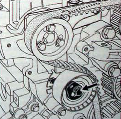
Pic. 4.10. Location of the timing belt tension roller bolt
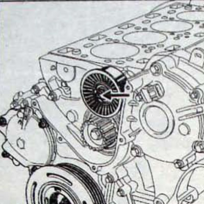
Pic. 4.11. Location of the timing belt idler roller nut
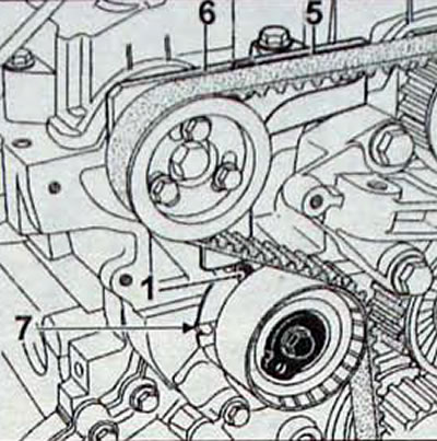
Pic. 4.12. Installing the timing belt: 1 - movable mark; 5 - rib; 6 - edge of the fixed part of the device Mot. 1537; 7 - groove of automatic tension roller
Installation
- Install the idler roller.
- Install the automatic tension roller without tightening the bolt securing it and ensuring the correct position of the groove (7. fig. 4.12) roller on a cotter pin.
- Screw, without completely tightening, the three bolts into the middle of the slots of the intake camshaft timing pulley.
- Install tool Mot. 1537 days of adjustment of the distribution valve exhaust valves.
- Make sure that the crankshaft is locked in the TDC position of the piston of the 1st cylinder.
- Install the timing belt together with the exhaust camshaft timing belt pulley, also placing the pulley mounting bolts in the middle of its slots.
- Operating principle of the device for adjusting and fixing the exhaust camshaft: movable mark (1, fig. 4.12) presses on the bottom end (3. fig. 4.13) staples (2). There are two ribs on the upper edge of the bracket (4) And (5), which when combined with the edge (6) the fixed part of the device repeats the position of the tension roller indicator.
- Adjust the position of the tension roller by turning the roller eccentric counterclockwise, then about 5°more. matching edges (5) And (6).
- Tighten the bolt (1. fig. 4.14) tension roller mountings and bolts (2) fastening the camshaft toothed pulleys with a torque of 10 Nm.
- Remove the camshaft adjusters Mot. 1534 and Mot 1537 and TDC lock Mot. 1536.
- Turn the crankshaft two turns clockwise.
- Lock the crankshaft at TDC with the TDC mark on the accessory crankshaft pulley aligned with the vertical axis of the engine.
- Install accessories Mot. 1534 and Mot. 1537 for adjusting the position of camshafts.
- Make sure that the tool foot Mot. 1537 moves freely vertically.
- Loosen the camshaft timing pulley bolts by no more than one turn.
- Checking the timing belt tension and camshaft adjustment
- Loosen the bolt (1, fig. 4.14) fastening the tension roller, holding the eccentric with a 6 mm hex key.
- Turn the tension roller eccentric clockwise until the end of the rib is aligned (3, fig. 4.14) paws (4) with top edge (5) fixed part of the device Mot. 1537.
- Tighten the tension roller mounting bolt to a torque of 25 Nm (pic. 4.14).
- Tighten the bolts securing the camshaft timing pulleys to a torque of 10 Nm (pic. 4.14).
- Remove tools Mot. 1534 and Mot. 1537 for adjusting the position of the camshafts and TDC lock Mot. 1536.
- Screw the plug into the top dead center clamp hole by applying a small amount of RHODORSEAL 5661 to the threads of the plug and tighten it to 22 Nm.
- Further installation is carried out in the reverse order of removal.
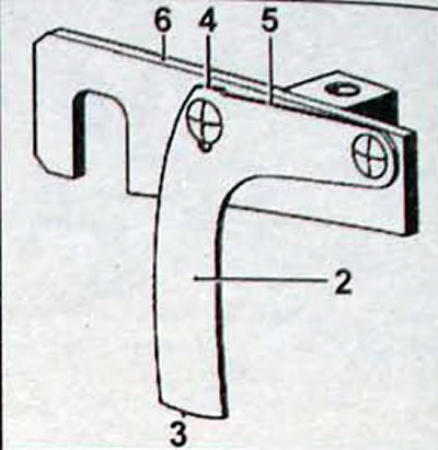
Pic. 4.13. Tool Mot 1537: 2 - bracket; 3 - lower end of the device; 4 - rib; 5 - rib; 6 - edge of the fixed part of the device Mot. 1537
Pic. 4.14. Adjusting the timing belt tension: 1 - tension roller mounting bolt; 2 - camshaft pulley mounting bolt; 3 - rib; 4 - foot; 5 - edge of the fixed part of the device Mot. 1537