
- The engine stop unit, controlled by the fuel injection control unit, is equipped with an intake air throttle valve that closes when the ignition is turned off, thereby stopping the engine quickly.
- An exhaust gas recirculation solenoid valve is also installed in the engine stop block housing
Removal
- Place the vehicle on a two post lift.
- Disconnect the cable from the negative terminal of the battery
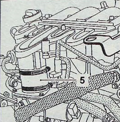
- Remove the engine oil pan protection and the air duct leading from the heat exchanger to the engine stop block. having previously disconnected the wire connector from the engine stop unit.
- Use a clamp to pinch the return line connecting the fluid reservoir to the power steering pump and disconnect the line from the pump.
- Remove the hydraulic power steering reservoir from the mount without disconnecting it from the pump, and place the reservoir on the side member.
- Remove the bolts securing the air duct going from the turbocharger to the heat exchanger and cylinder head (pic. 4.34).
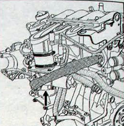
Pic. 4.33. Engine stop block housing location
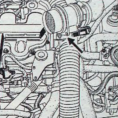
Pic. 4.34. Location of the bolt securing the air duct going from the turbocharger to the heat exchanger and cylinder head
- Remove the reinforcement arm (1, fig. 4.35), connecting the housing of the turbocharger engine stop block with the bracket of the power steering pump.
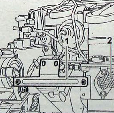
Pic. 4.35. Location of the booster arm on the engine (1) and exhaust gas recirculation hose (2)
- Remove the exhaust gas recirculation hose as well as the sealing gaskets. When installing the air path, replace the hose and gaskets
- Disconnect the connector from the EGR control solenoid valve.
- Unscrew the bolt securing the foot (3, fig. 4.36) air conditioner low pressure pipe.
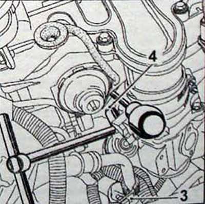
Pic. 4.36. Location of the foot mounting bolt (3) and turning out the bolt (4) throttle body mounting
- Remove the bolts securing the throttle assembly to the engine cylinder block. To do this, use a 13 mm socket. universal joint and a small extension. If necessary, move the pipelines to the side to gain access to the bolts.
Attention. Do not remove self-tapping screws (A, fig. 4.37) fastening the upper part to the throttle body.
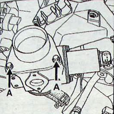
Pic. 4.37. Location of self-tapping screws (A) attaching the upper part to the throttle body
- Remove the pipe (1. fig. 4.38), connecting the throttle assembly to the intake manifold.
Pic. 4.38. Location of pipe mounting clamps (1), connecting the intake manifold to the turbocharger engine stop block and lugs (2)
- To make it easier to remove the engine stop block, disconnect the electrical wiring harness located in front of the engine stop block housing from the fasteners
Installation
- Installation is carried out in the reverse order of removal.
- Tighten the fastening clamp nuts to a torque of 55 Nm.
- Using the diagnostic tool, check whether stored fault codes have been recorded and delete the codes if any.