



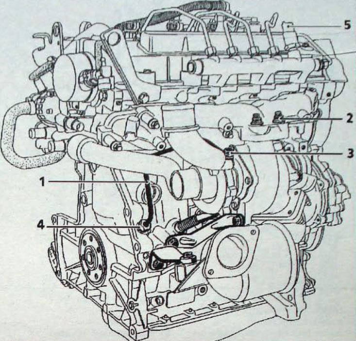
Fig. 4.31. Turbocharger fastening and connection elements on the G9T engine: 1 - oil supply line to the turbocharger; 2 - nut, 27 Nm; 3 - nipple; 4 - nipple; 5 - fuel pressure sensor in the distribution line
- Removal and installation a turbocharger requires removing the power unit from the vehicle.
Caution: Do not attempt to remove the turbocharger without removing the power unit under any circumstances, as this will make it impossible to meet the requirements for connecting the oil supply line (1, Fig. 4.31), and the stresses caused by blind tightening of the fitting (3) will lead to damage to the pipeline (1) when the engine is running.
- Install the pipe (1) onto the turbocharger by tightening the fitting (3) by hand.
- Install the turbocharger, making sure the nipple (4) is in the correct position and tightening it by hand.
- Tighten the turbocharger to manifold mounting nuts to 27 Nm.
- Tighten the nipple (4), then the nipple (3).
- The special sealing gasket of the oil supply nipple (3) to the turbocharger must be replaced.
- Before starting the engine, disconnect the fuel pressure sensor wire connector in the fuel distribution line (5). Then turn on the starter for a few seconds until the oil pressure indicator lamp goes out.
- Connect the sensor wire connector, turn on the pre-heater and start the engine.
- Let the engine idle and check for leaks at the turbocharger oil line fittings.
- Using the diagnostic device, delete from memory the recorded fault code, the code of which was registered when the sensor was disconnected.
Original version on our portal [RENAULTBOOK.ru]
Precautionary measures
- Make sure that no foreign objects get into the turbine or compressor. If the turbocharger is faulty, check whether the air-to-air heat exchanger is filled with oil, otherwise remove the heat exchanger, wash it with a cleaner and drain the cleaner thoroughly.
- Make sure that the oil drain channel is not partially or completely clogged with carbon deposits. Also make sure that it is completely sealed, otherwise replace it.
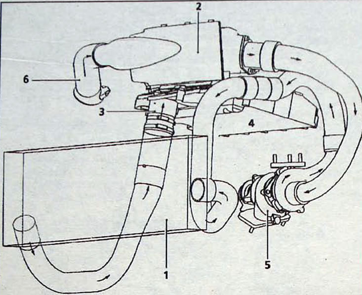
Fig. 4.32. Elements of the air supply system:1 - air-to-air heat exchanger; 2 - air filter;3 - Engine stop block housing; 4 - intake manifold; 5 - turbocharger; 6 - suction pipe