
- When removing the upper mount housing, limit rod, or bracket attached to the suspension mount cup, follow the procedure below for tightening the threaded connections of the removed parts.
- Carry out installation in the following sequence:
- install the limiter rod bracket (1, fig. 4.42) onto the shock absorber mounting cup and tighten the bolts (A) torque 30 Nm;
- install traction (2) on the bracket (1), without tightening the fasteners;
- install an elastic cushion (3) onto the suspension strut mounting cup and tighten the bolts (WITH) torque from 50-65 Nm; install the upper casing of the pendulum support (4) on a rubber cushion (3) and connect it to the rod (2). Tighten the bolt to 105 Nm (IN) rod fastenings (2) to the bracket (1).
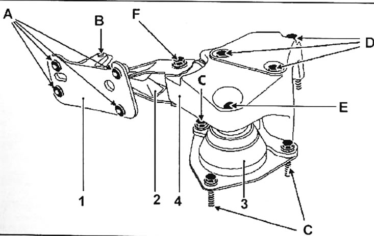
Pic. 4.42. Pendulum suspension supports: A - bolt, 30 Nm; B - bolt, 105 Nm; C - bolt, 50-65 Nm; D - bolt, 62 Nm; E - bolt, 62 Nm; F - bolt, 105 Nm; 1 - bracket; 2 - traction; 3 - elastic pillow; 4 - upper casing of the pendulum suspension support
- Install the engine and tighten the 62 H bolts (D) securing the upper casing to the engine.
- Tighten the bolt to 62 Nm (E) attaching the upper casing to the rubber cushion (3) and torque 105 Nm - bolt (F) rod fastenings (2) to the top casing (4).