
Attention
- Before carrying out any work on the fuel distribution line, connect the diagnostic tool, establish communication with the injection system control unit and ensure that the fuel distribution line is not under pressure.
- Take precautions against possible burns from hot fuel.
Removal
- Disconnect the cable from the negative terminal of the battery.
- Remove the air filter and sound insulation of the engine compartment partition. To remove the sound insulation, it is necessary, without disconnecting it, to remove the solenoid valve for adjusting the pressure of the turbocharger. installed on the partition of the engine compartment.
- Remove the fuel line at the turbocharger inlet by disconnecting the crankcase ventilation pipe.
- Remove the side partitions of the rubber apron. Disconnect the rubber apron from the engine mount, and then from the cylinder head cover and move it as far back as possible.
- While holding the studs, unscrew the two nuts, remove the cylinder head cover sealing baffle and remove the porous absorbent gaskets.
- Blow out the top of the engine with compressed air.
- Remove the oil filler neck and the air filter mounting tab on the left side of the engine. Cover the oil filling hole with a clean rag.
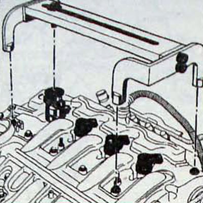
- Disconnect the connector from the pressure sensor (1. fig. 4.58).
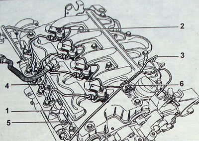
Pic. 4.58. Location of fuel system elements: 1 - pressure sensor; 2 - diesel fuel return hose from the injectors; 3 - fuel injection pipes; 4 - injector pipes; 5 - fuel distribution line mounting bolts; 6 - clamp
- Disconnect the rubber hose (2) return of diesel fuel from injectors
- Remove the fuel injection pipes (3). connecting the high pressure pump and the fuel distribution line. When removing the lock (6) mounted on the cylinder head, be careful as it is very fragile.
- Remove the injector tubes (4).
- When unscrewing the union nut (1. fig. 4.59) fastening the fuel injection pipe to the injector body, it is necessary to hold the nut with a second wrench (2) filter mounting. Plug the holes with plugs.
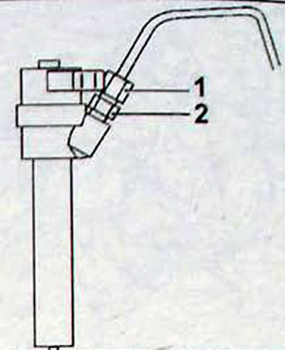
Pic. 4.59. Attaching the tube to the fuel injector: 1 - union nut; 2 - filter mounting nut
- Unscrew the bolts (5. fig. 4.58) fuel rail, but do not remove it.
- Remove the mounting bolts for each injector housing.
- To remove the injectors* use tool Mot. 1549 (pic. 4.60). Never attempt to remove an injector body that is secured in its seat in the cylinder head without using tool Mot. 1549. Apply a special compound around the nozzle. Install the puller onto the injector body. Rotating the knurled puller ring, bring both puller jaws to the flats of the nozzle body and squeeze the jaws without applying significant force (pic. 4.61).
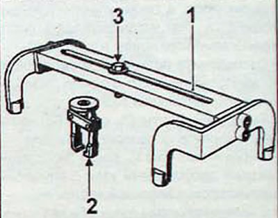
Pic. 4.60. Tool Mot 1549: 1 - puller mounting frame, installed on the cylinder head cover mounting bolts; 2 - nozzle puller; 3 - puller mounting bolt
Pic. 4.61. Installing tool puller Mot. 1549 per injector
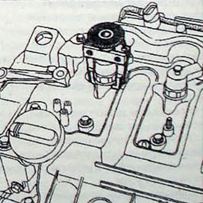
- Install the frame of tool Mot 1549 onto the cylinder head cover bolts (pic. 4.62). Tighten the puller bolt until it is possible to remove the injector from the cylinder head.
Pic. 4.62. Installing tool frame Mot. 1549 for cylinder head cover bolts
- Remove all washers from the injector seats.
Installation
- For any operation, remove the protective plugs immediately before installing the part in place.
- Wash the injector seats and the injectors themselves, as well as their flanges, using a lint-free cloth soaked in fresh solvent.
- Pat all elements dry with another fresh napkin.
- Clean the internal thread by rinsing one of the used injector mounting bolts and tightening it to the end of the thread.
- Screw in the new studs and install the injector mounting spacers, having first lubricated their threads with oil, and then hand-tighten them to the end of the threads. The studs and nuts should be replaced with each disassembly.
- Install a new washer onto the injector lip.
- Reinstall the injector using the flange and snap ring.
- Lubricate the threads of the nuts.
- Tighten the nuts (oiled) torque 6 Nm, first from the gas distribution mechanism drive side. and then from the flywheel side of the engine.
- Tighten only the nut on the engine flywheel side to an angle of 360±30g
- Clear the fuel line. To do this, unscrew the three bolts securing the line.
- Remove the plugs from the line, injector housings and fuel injector lines
- Connect the fuel injector lines between the line and the injectors, first tightening the connections between them by hand until they touch
- Torque tighten
- 23 Nm three bolts securing the line,
- 25 Nm fittings of the fuel injection lines at the injectors and at the high pressure pump;
- 25 Nm fittings of the fuel injection lines at the line.
- Install the pump/line fuel line retainer and secure it with two bolts
- Install the sealing partition in place, securing it with two nuts on the cylinder head cover.
- Install the main line protection side partitions in place.
- Move forward and install the rubber line protection apron in place.
- During any work with the highway protection system, you should ensure that after installing all the elements that make up this system, the latter are exactly in their places. Failure to follow these instructions may result in serious consequences.
- Further installation is carried out in the reverse order of removal.
- Using a diagnostic tool, check for stored fault codes and, if present, clear them.
- After carrying out any work, check that there are no leaks from the diesel fuel supply circuit. Let the engine idle until the electric cooling fan turns on, then increase the engine speed several times while idling.