
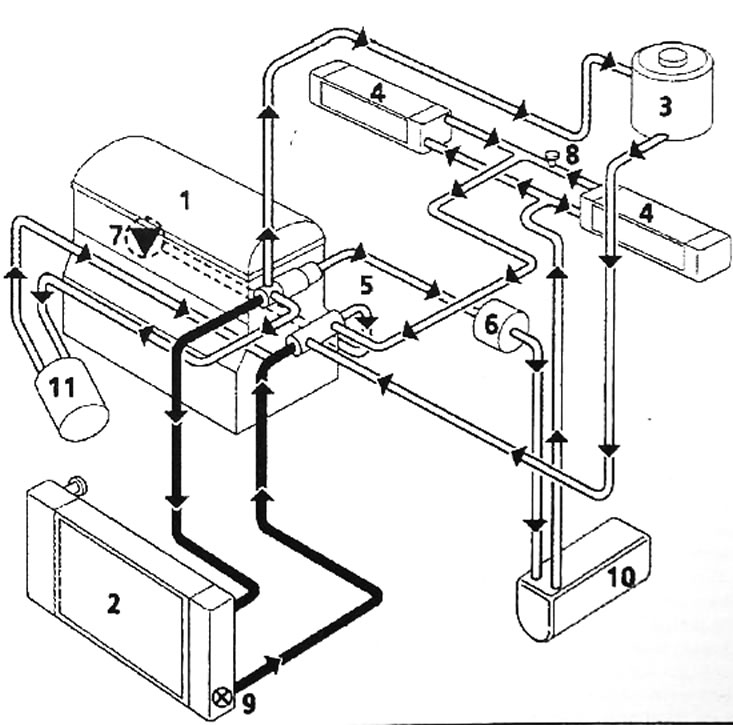
Pic. 4.70. Engine cooling system diagram: 1 - engine; 2 - radiator; 3 - expansion tank with degassing valve after the thermostat; 4 - heater radiators; 5 - thermostat bracket; 6 - bracket for thermal valves; 7 - water pump; 8 - air removal valve; 9 - thermal relay; 10 - additional heater heater (if installed); 11 - oil heat exchanger and oil filter
The closed cooling system includes a water pump, radiator, radiator fan with electrical wire, thermostat, heater core, hoses and sensors. The radiator fan with electric wire is switched on when the contact temperature sensor is activated. On models with an automatic transmission, some of the fluid circulates through the transmission fluid heat exchanger. Coolant circulates through the heater radiators constantly.